
Cutting Tool with a Replaceable Blade Edge

Active Publication Date: 2012-09-13
TUNGALOY CORP
View PDF12 Cites 7 Cited by
  • Summary
  • Abstract
  • Description
  • Claims
  • Application Information

AI Technical Summary

Benefits of technology

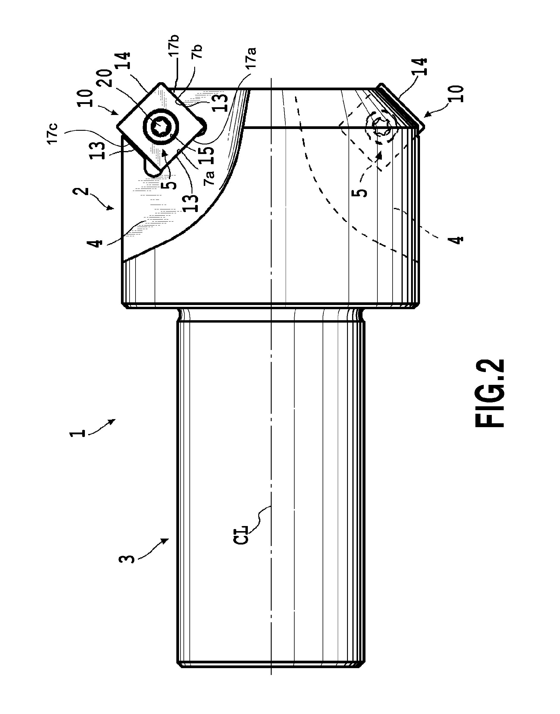
[0017]According to this embodiment, the one of the two peripheral faces in the cutting insert contacts the first restraint wall face in a substantially parallel posture with the extending direction of the first restraint wall face. That is, the one of the peripheral faces makes line contact or surface contact with the first restraint wall face along the extending direction of the first restraint wall face. The other peripheral face is inclined relative to the extending direction of the second restraint wall face, and contacts the second restraint wall face at one end portion of the second restraint wall face. That is, the other peripheral face makes point contact or line contact with the second restraint wall face at one end portion of the second restraint wall face. In the cutting insert attached in the insert attachment seat, the one peripheral face is thus restrained in a state in parallel with the extending direction of the first restraint wall face, and therefore the attachment precision and the attachment stability of the cutting insert to the insert attachment seat are improved. Thereby the positioning precision of the cutting edge for cutting the configuration part to the tool body and the processing precision of the configuration part are improved.
[0018]According to the present invention, the attachment precision and the attachment stability of the cutting insert are improved. The positioning precision of the cutting edge of the cutting insert to the tool body and the processing precision of the configuration part cut by the cutting edge are improved.

Problems solved by technology

However, at the time of screwing the fastening screw, the cutting insert is subjected to a rotational moment in a rotational direction of the fastening screw by contact between the fastening screw and the inner peripheral face of the attachment hole, and may be forcibly rotated in the rotational direction of the fastening screw in the insert fastening seat.
Therefore since the cutting edge of the cutting insert can not be correctly positioned to the cutting body, the precision of a chamfered portion cut by this cutting edge is also deteriorated.
Therefore looseness of the fastening screw is generated, causing further rotation of the cutting insert, and in the worst case there is a possibility that breakage of the cutting edge is generated or the cutting insert falls down from the insert attachment seat.

Method used


Image

  • Cutting Tool with a Replaceable Blade Edge
  • Cutting Tool with a Replaceable Blade Edge
  • Cutting Tool with a Replaceable Blade Edge

Examples


Embodiment Construction

[0028]Hereinafter, a chamfering cutter of an embodiment of the present invention will be described with reference to the drawings.

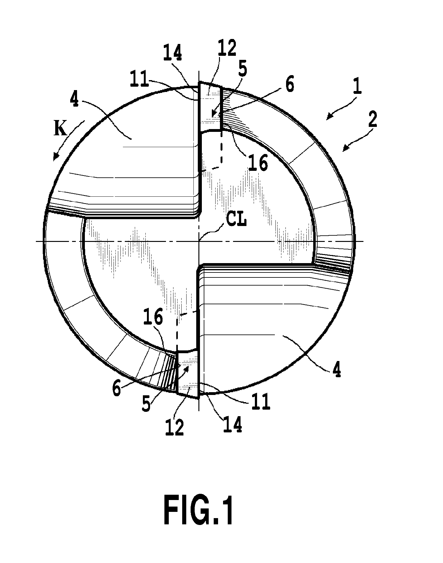
[0029]As shown in FIG. 1 to FIG. 3, a chamfering cutter of the present embodiment is structured such that a cutting insert 10 having cutting edges 13 is removably installed in an insert attachment seat 5 formed in a front end peripheral portion of a tool body 1. The tool body 1 is formed in a substantially cylindrical shape to rotate around a center axis line CL. A shank 3 is formed in a rear end side (left side in FIG. 2) for installing the tool body 1 in a machine tool such as a machining center, and a cutting head 2 in which the insert attachment seat 5 is provided is formed in a front end side (right side in FIG. 2) of the tool body 1.

[0030]Chip pockets 4 are formed on a peripheral surface of the cutting head by notching it in such a manner as to extend from a front end face toward a rear end face of the cutting head 2. The insert attachment seat 5 is...


PUM

PropertyMeasurementUnit
Angleaaaaaaaaaa

Abstract

As viewed from a side opposing a bottom face (6) of an insert attachment seat, an angle (α) between first and second restraint wall faces (7a) and (7b) rising from the bottom face (6) is smaller than an angle (β) between two peripheral faces of a cutting insert contacting them respectively. A first peripheral face of the cutting insert contacts the first restraint wall face (7a) in a substantially parallel posture with the extending direction of the first restraint wall face (7a), while the second peripheral face contacts the second restraint wall face (7b) in an end portion of the second restraint wall face (7b).

Description

CROSS-REFERENCE TO RELATED APPLICATIONS[0001]This application is a continuation-in-part of PCT application No. PCT / JP2010 / 071809, filed Dec. 6, 2010 and published as WO 2011 / 071007A1 on Jun. 16, 2011, and which claims priority to Japanese Patent Application No.2009-278296, filed Dec. 8, 2009. The contents of the aforementioned applications are incorporated by references in their entirety.BACKGROUND OF THE INVENTION[0002]1. Field of the Invention[0003]The present invention relates to a tip-replaceable cutting tool in which a cutting insert is removably installed, in particular for cutting a configuration part.[0004]Description of the Related Art There is conventionally known a so-called screwed type of cutting tool in which a cutting insert having cutting edges is removably installed to a tool body by using a fastening screw such as a countersunk screw. This type of cutting tool is put into practical use in finish processing to a configuration part of a work piece. An example of the ...

Claims


Application Information

Patent Timeline
IPC IPC(8): B23B51/00
CPCB23C5/109B23C5/2208B23C2210/168Y10T408/909B23C5/20B23D31/003B23C2220/16B23C5/202
Inventor UNO, KAZUYUKINISHIYA, NAOTO
Owner TUNGALOY CORP
Learn More