Water Containment System

a technology of water containment and water containment pipe, which is applied in the field of temporary water containment pipe, can solve the problems of lack of practicality, lack of water containment pipe, and low water containment pipe support, and achieves the effects of light weight transportation, simplified field erection, and low cos

Inactive Publication Date: 2012-09-13
ROWLAND LYLE R +1
View PDF34 Cites 14 Cited by
  • Summary
  • Abstract
  • Description
  • Claims
  • Application Information

AI Technical Summary

Benefits of technology

[0028]An embodiment of the present invention is a supporting structure, a membrane support plate, and a water membrane which contacts the water and contains it. The supporting structure is light weight in design, and alternates in three primary parts: an end support frame and a middle supporting frame. A top supporting frame is also included in many embodiments, but not in all. The design features simplified field erection, light weight transportation, and an efficient design for following a field directed path without the use of surveyors.
[0029]An important embodiment of the present invention includes additional structures which allow convenient methods to turn the support structure and membrane support plate in a way that allows the water containment system to follow a curved path rather than o...

Problems solved by technology

Conventionally, sandbags and earthen berms or dams are used in these situations to form dikes to contain the water, however, these methods are time consuming and very labor intensive.
U.S. Pat. No. 6,676,333 by Wiseman et al is an attempt to provide a temporary type of structure, but it lacks practicality due to the frequent support structures, and the membrane used to contain the water is poorly supported.
As a practical matter, it is not very portable or mobile.
U.S. Pat. No. 6,132,140 by Kullberg is another attempt to provide a temporary type of structure, but it also lacks practicality and economy due to the excessive weight/design of the membrane support face, which is very heavy.
Also, the design lacks consideration to ensure that a multi-curve path can be followed.
The design is very heavy, complicated, and the pipe/rod system requires field bending.
Field installation is labor intensive; requiring training and special tools.
The design is complicated and it is questionable that the design would be stable under actual hydrostatic pressure conditions.
The design is very complicated, heavy, and needs soil for weight to stabilize the base.
The system is difficult and unappealing to utilize in the event of a natural disaster where it needs to be installed by a flood.
The design is overly complicated for a temporary dam system requiring an excessive amount of work to fill the various structures with water in place.
Sandbags are a method to bui...

Method used


Image

  • Water Containment System
  • Water Containment System
  • Water Containment System

Examples


Embodiment Construction

[0040]This application incorporates by reference the entirety of Canadian Application No. CA 2628067, filed on Apr. 2, 2008.

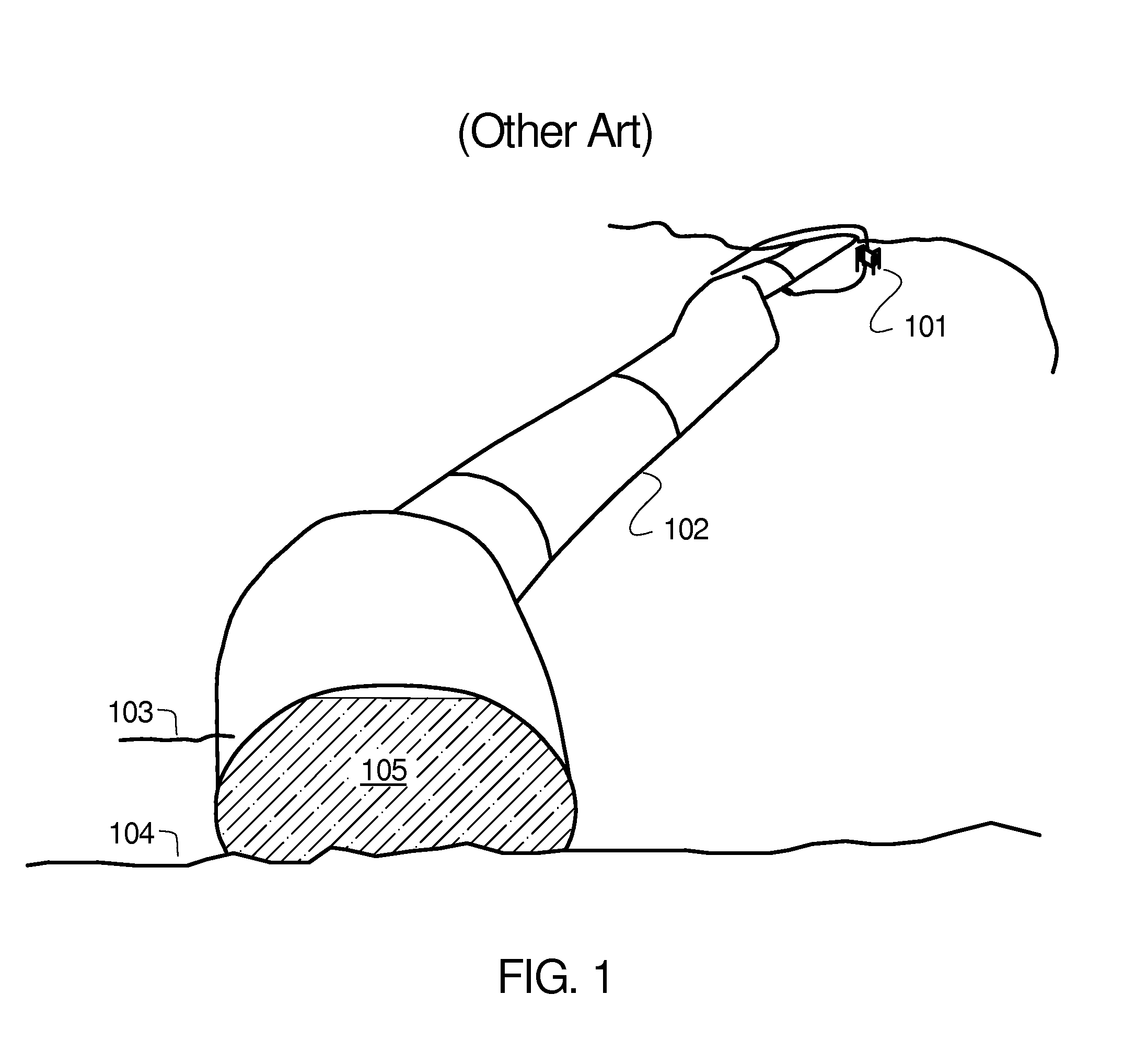
[0041]FIG. 1 illustrates another art design where an inflated water dam is used to retain low water levels of a lake or dam spillover. A pump 101 is used to fill an elastomer tube 102 which is nearly filled with water 105 to hold back a water level 103 on a lake or river bed surface 104. This device has some advantages in rapid deployment, but is offset by disadvantages in sliding on the lake bed due to hydrostatic pressure when the water level is high, and seepage underneath the elastomer tube.

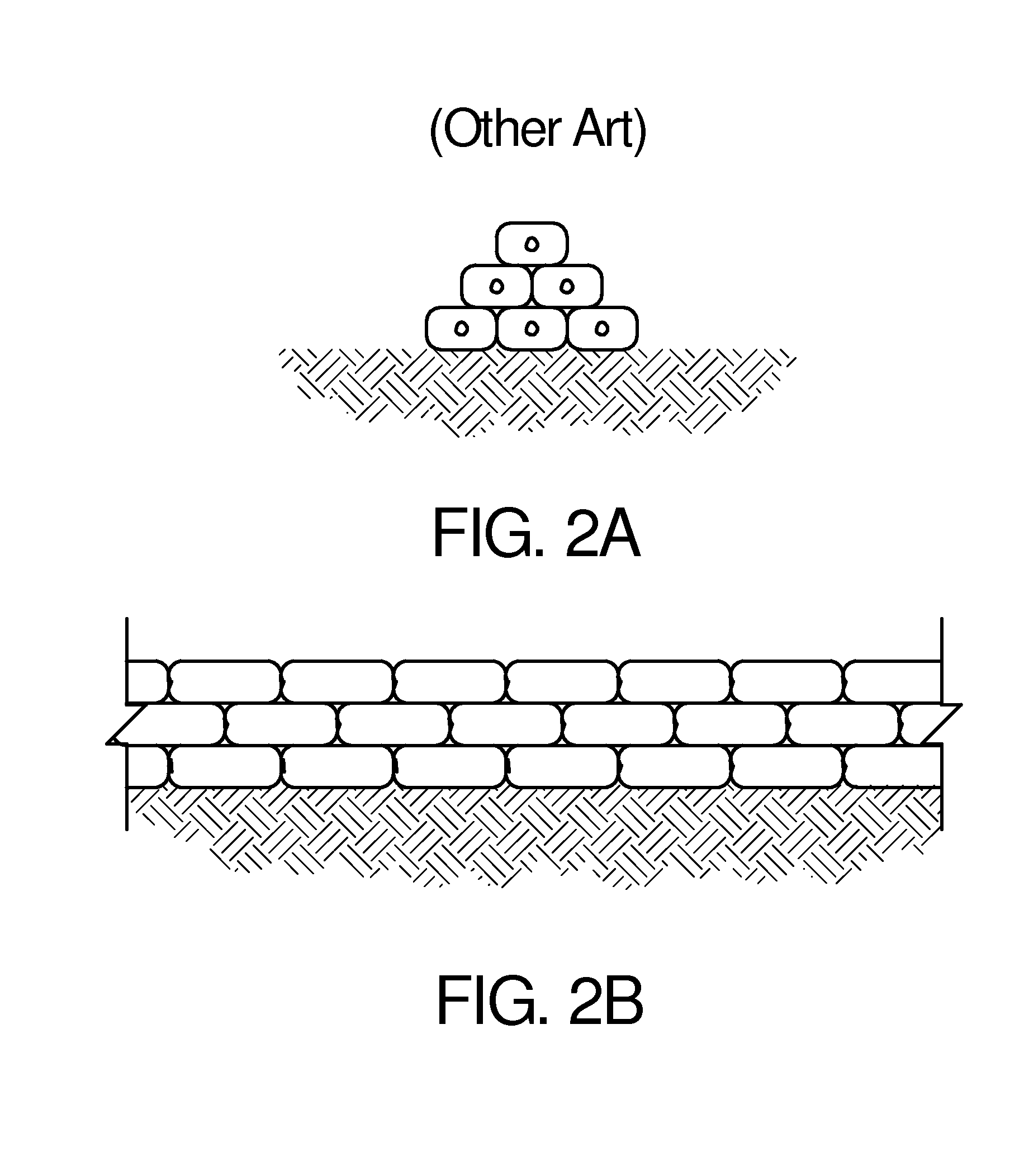
[0042]FIG. 2A-2B illustrate a common method of stacking sandbags for a portable dam where the sandbags are stacked in an alternate manner, both in height and depth so that the top sandbag row has a large supporting base. Other stacking arrangements are common and the top row may have a larger or more narrow base, depending upon the local conditions. FIG. 2A is a cross se...


PUM


Abstract

A temporary dam system for containing a body of water is provided. The temporary dam system is constructed with a number of dam sections. Each dam section has three or more supports and a back brace for supporting a resistant membrane backed by a plate. The supports comprise an end support, a middle support, and a top support in an A-frame structure. A membrane backing plate is attached to the front of the assembled support structure. The overall containment dam system is constructed by connecting dam sections together to form a continuous wall of rigid plates facing a body of water. A flexible liquid-impervious membrane is then placed over the rigid plates to contain the water.

Description

CROSS REFERENCE TO RELATED APPLICATIONS[0001]Not applicable.STATEMENT REGARDING FEDERALLY SPONSORED RESEARCH OR DEVELOPMENT[0002]Not applicable.REFERENCE TO SEQUENCE LISTING, A TABLE, OR COMPUTER PROGRAM LISTING[0003]Not applicable.BACKGROUND OF THE INVENTION[0004](1) Field of the Invention[0005]This application is directed to field of temporary water containment dams and more particular a portable system that can be assembled into a temporary water containment dam.[0006](2) Description of Related Art[0007]Temporary dams or dikes are often needed to hold back water, whether for emergency flood control, water diversion, repairs to structures normally surround or covered by water such as bridges or banks, construction projects, etc. Conventionally, sandbags and earthen berms or dams are used in these situations to form dikes to contain the water, however, these methods are time consuming and very labor intensive.[0008]U.S. Pat. No. 6,676,333 by Wiseman et al is an attempt to provide a...

Claims


Application Information

Patent Timeline
IPC IPC(8): E02B7/08E02B7/20E02B7/02
CPCE02B3/106Y02A10/11
Inventor ROWLAND, LYLE R.HALLICK, BRIAN
Owner ROWLAND LYLE R
Why Eureka
Try Eureka