
Pod for space or near-space flights

a space or near-space flight technology, applied in the field of human flight, can solve the problems of space tourists further suffering discomfort, sub-orbital flights are still projected to be very costly, and the demand for space tourism will be very small at these steep prices, so as to achieve less sudden movements and shocks

Active Publication Date: 2012-09-13
ZERO2INFINITY
View PDF21 Cites 16 Cited by
  • Summary
  • Abstract
  • Description
  • Claims
  • Application Information

AI Technical Summary

Benefits of technology

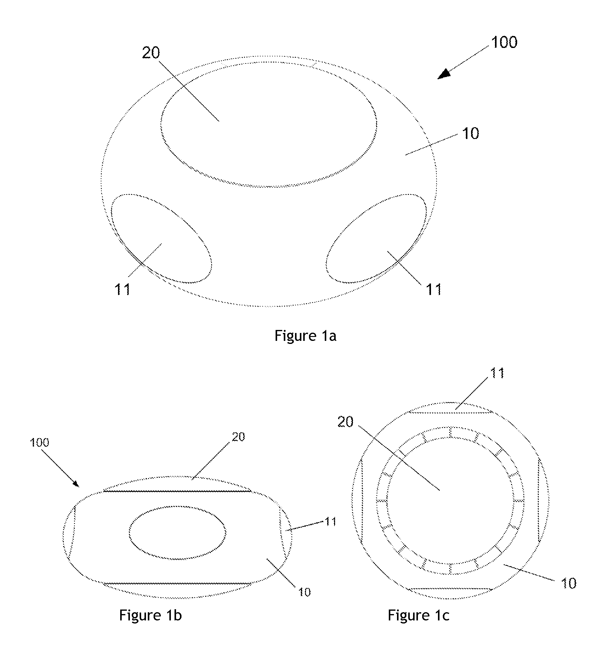
[0012]The pressurized substantially ring-shaped body comprises an internal surface substantially facing said central axis, and an external surface, substantially facing away from said central axis. Preferably, one or more windows are provided on said external surface. On the external surface of the ring (surface facing away from the central axis), the stresses in the structure due to internal pressurization will generally be lower than on the internal surface of the ring. By predominantly providing the windows on the external surface, the stresses due to inevitable stress concentrations around the windows can be kept to a minimum. This makes it possible to provide relatively large windows for the viewing pleasure of the passengers. It even makes it possible to provide a single large window prescribing the entire circumference of the pressurized body. More preferably, with the goal of minimizing stresses, the windows are located on the part of the external surface furthest away from the central axis.
[0018]Preferably, all systems relating to accelerating or decelerating the pod are connected to the non-pressurized body so that loads related to acceleration or deceleration are introduced into the pod via the non-pressurized body. One way of using the pod for space tourism that is foreseen consists in ascending to an altitude of between 30 km-40 km above the Earth with the help of a balloon. After a stay at this altitude, the pod returns to the Earth with the help of a parachute-like structure. For the landing on Earth, an airbag-like structure may be foreseen. In this case, accelerations experienced by the gondola may be caused by the balloon, the parachute or the airbags. By attaching these systems at the non-pressurized body, the loads related to these decelerations and accelerations are introduced into the pod in said non-pressurized body. By providing a motion-damping structure between the pressurized body (housing the passengers and optionally crew) and the non-pressurized body, the passengers will experience less sudden movements and shocks.
[0021]In some embodiments of the invention, said pressurized body may comprise a shape obtained by revolving a geometrical figure around an axis of revolution external to that figure. An example of such a shape is a torus, which is obtained by revolving a circle around an axis of revolution. The advantage of a torus-shaped pod is that, while maintaining a suitable set-up for hosting passengers, stresses in the structure due to the pressurization may be minimized. In some embodiments, instead of a torus, the shape of the pod is obtained by revolving a more elliptical figure around an axis of revolution. As long as a substantially rounded geometrical figure is used, stresses in the structure can be kept relatively small. A slightly less rounded shape may be advantageous as well, depending on e.g. the interior design of the pod, the connection with the non-pressurized body etc.

Problems solved by technology

It is obvious however, that the demand for space tourism will be very small at these steep prices.
Apart from the high prices, another factor that might discourage potential space tourists is the long training period necessary before being allowed to fly.
Space tourists may further suffer discomfort when experiencing prolonged weightlessness.
These sub-orbital flights are however still projected to be very costly.
Furthermore, with available jet and rocket technology, it can be foreseen that the emissions from these vehicles will be potentially damaging to the environment in general and the ozone layer in particular.
These prior art systems are hardly suitable for commercial flights: the space available for passengers is very small, the windows are very small (practically inevitable with the shape of the gondola), and although some shock absorbing structure has been provided to soften the landing, the trip will hardly be pleasant for passengers.

Method used


Image

  • Pod for space or near-space flights
  • Pod for space or near-space flights
  • Pod for space or near-space flights

Examples


Embodiment Construction

[0031]FIGS. 1a-1f illustrate embodiments of a first type of pod according to the present invention. A pod 100 according to the present invention comprises a pressurized body 10 for hosting passengers (“space tourists” and optionally pilots and further crew). Said pressurized body is provided with a plurality of windows 11. The pressurized body 10 in this embodiment is formed by a toroid (or “donut” shape), more clearly illustrated in FIGS. 1d and 1e.

[0032]The toroid is formed around a central axis of revolution 7. In the central opening, indicated with reference sign 5 in FIG. 1e, the non-pressurized body 20 may be located.

[0033]The windows 11 have advantageously been provided on the external surface 10b of the pressurized body (the part of the surface of the pressurized body that faces away from the central axis 7). The stress concentrations around the windows 11 will be relatively small, since the prevailing stresses in the external surface 10b are smaller than in the internal su...


PUM


Abstract

A pod (100) for flights to and / or from space or near-space, comprising a pressurized body (10) for hosting passengers, said pressurized body having a substantially ring-like shape provided around a central axis (7) and having a central opening, wherein said pressurized body comprises one or more windows.

Description

TECHNICAL FIELD[0001]The present invention relates to human flight at great altitude, and more particularly to a pod for space and / or near-space flight.BACKGROUND OF THE INVENTION[0002]Human spaceflight has been around for many years. For example, U.S. Pat. No. 3,093,346 discloses a manned capsule which can be lifted into orbit by a launching motor. The capsule can subsequently return to Earth using a parachute system. Another example is known from U.S. Pat. No. 3,702,688 which discloses a booster vehicle to inject an orbiter into orbit. Both the booster vehicle and the orbiter are provided with crew compartments.[0003]Human spaceflight has until recently been the exclusive domain of governmental or intern-governmental space agencies. However, at the end of the 1990's the phenomenon of space tourism emerged.[0004]Until the day of today, about a handful of wealthy individuals have paid for a flight with a spacecraft to the International Space Station (ISS) and a subsequent stay in th...

Claims


Application Information

Patent Timeline
IPC IPC(8): B64G1/00
CPCB64G1/002B64G1/005B64G1/12B64G2001/224B64G1/60B64G1/62B64G1/58B64G1/2227B64G1/625B64G1/623
Inventor LOPEZ URDIALES, JOSE MARIANO
Owner ZERO2INFINITY
Learn More