Fuel cell system
a fuel cell and system technology, applied in battery/fuel cell control arrangement, electrochemical generators, transportation and packaging, etc., can solve the problems of drivability (a maneuverability performance), the output following the accelerator response during a request for a high load cannot be obtained, and the cell voltage temporarily drops, etc., to achieve the effect of reducing the damage to the accumulator device due, surplus power, and not impaired drivability
- Summary
- Abstract
- Description
- Claims
- Application Information
AI Technical Summary
Benefits of technology
Problems solved by technology
Method used
Image

Examples
embodiment 1
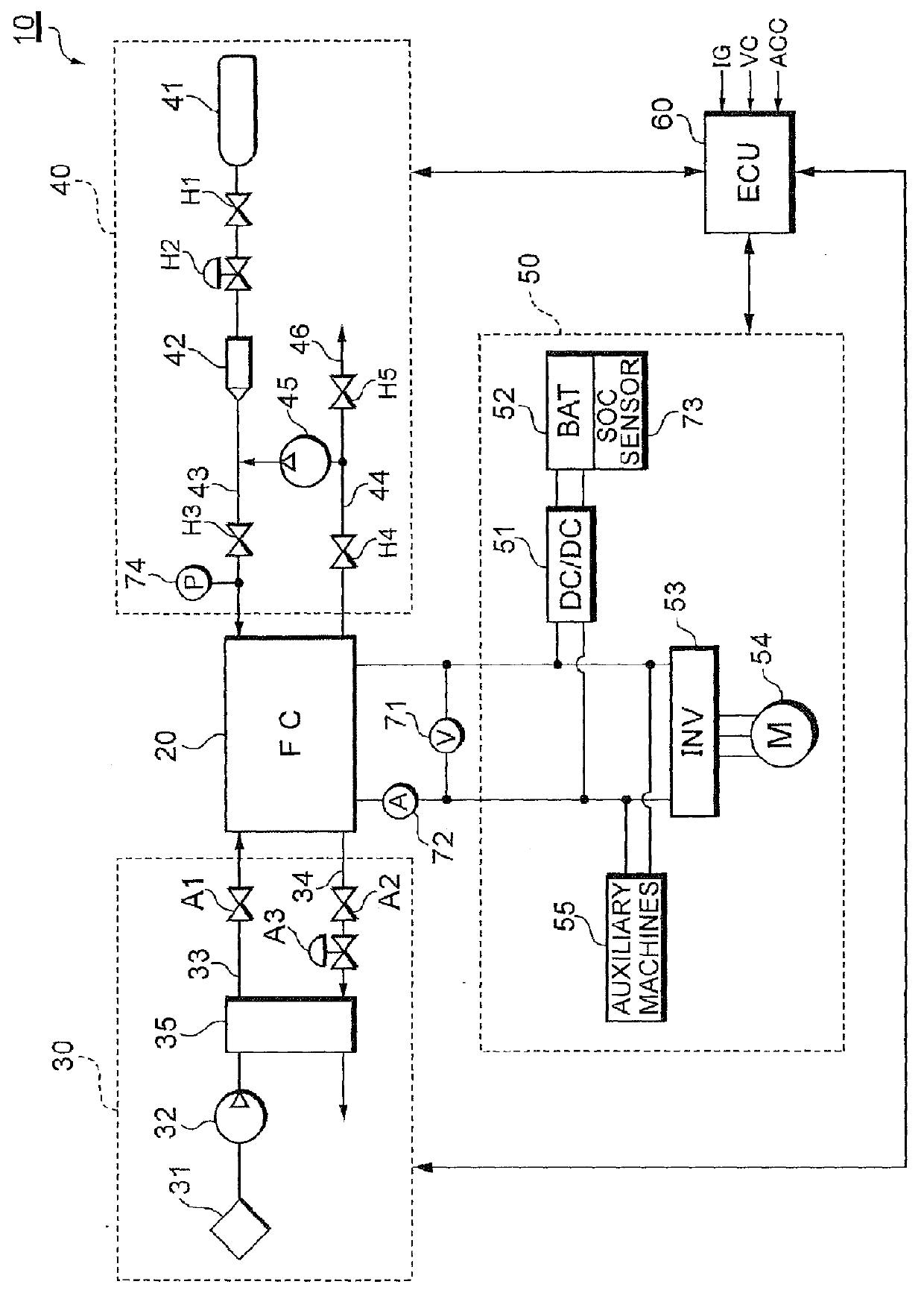
[0036]FIG. 1 shows a system constitution of a fuel cell system 10 according to Embodiment 1.
[0037]The fuel cell system 10 functions as a car-mounted power source system mounted on a fuel cell vehicle, and includes a fuel cell stack 20 which receives a supplied reactant gas (a fuel gas, an oxidizing gas) to generate a power; an oxidizing gas supply system 30 for supplying air as the oxidizing gas to the fuel cell stack 20; a fuel gas supply system 40 for supplying a hydrogen gas as the fuel gas to the fuel cell stack 20; a power system 50 for controlling charging / discharging of the power; and a controller 60 which generally controls the whole system.
[0038]The fuel cell stack 20 is a solid polymer electrolyte type cell stack in which a large number of cells are stacked in series. In the fuel cell stack 20, an oxidizing reaction of formula (1) occurs in an anode pole, and a reducing reaction of formula (2) occurs in a cathode pole. In the whole fuel cell stack 20, an electromotive reac...
embodiment 2
[0120]FIG. 15 shows a system constitution of a fuel cell system 11 according to Embodiment 2. The fuel cell system 11 has a constitution of a capacitor system in which a capacitor 57 is connected in parallel with a fuel cell stack 20 as a main power source, and a power generated by the fuel cell stack 20 or a regenerative power collected by a traction motor 54 during regenerating braking is charged into the capacitor 57. When the power is necessary for rapid acceleration or the like, the capacitor 57 momentarily takes out the power to realize the system constitution excellent in output characteristics.
[0121]A DC / DC converter 56 on a primary side is connected to an output terminal of the fuel cell stack 20, and the DC / DC converter on a secondary side is connected in parallel with the capacitor 57 and a traction inverter 53, respectively. When an operation is controlled in a first operation mode, a controller 60 turns off a relay 58, and controls the output voltage of the fuel cell st...
embodiment 3
[0123]FIG. 16 shows a system constitution of a fuel cell system 12 according to Embodiment 3. The fuel cell system 10 according to Embodiment 1 has a constitution of a parallel hybrid system in which the DC / DC converter 51 and the traction inverter 53 are connected in parallel with each other and connected to the fuel cell stack 20, whereas the fuel cell system 12 according to Embodiment 3 has a constitution of a series hybrid system in which a DC / DC converter 51 and a traction inverter 53 are connected in series with a fuel cell stack 20 as a main power source. Both the embodiments are different from each other in this respect.
[0124]It is to be noted that catalyst activation processing in the fuel cell system 12 according to Embodiment 3 is similar to that of Embodiment 1.
[0125]It is to be noted that in the above embodiments, a utilizing configuration in which the fuel cell system 10 is used as the car-mounted power source system has been illustrated, but the utilizing configuratio...
PUM
| Property | Measurement | Unit |
|---|---|---|
| voltage | aaaaa | aaaaa |
| reduction potential | aaaaa | aaaaa |
| power | aaaaa | aaaaa |
Abstract
Description
Claims
Application Information
 - R&D
- Intellectual Property
- Life Sciences
- Materials
- Tech Scout
- Unparalleled Data Quality
- Higher Quality Content
- 60% Fewer Hallucinations
Browse by: Latest US Patents, China's latest patents, Technical Efficacy Thesaurus, Application Domain, Technology Topic, Popular Technical Reports.
© 2025 PatSnap. All rights reserved.Legal|Privacy policy|Modern Slavery Act Transparency Statement|Sitemap|About US| Contact US: help@patsnap.com