
Liquid dispensing device

a liquid dispensing device and liquid technology, applied in the field of pharmaceuticals, can solve the problems of troublesome leakage from the device, increased risk of leakage, and liquid leakage at the periphery of the diaphragm, and achieve the effect of improving sterility

Active Publication Date: 2012-09-06
NEMERA LA VERPILLIERE SAS
View PDF10 Cites 14 Cited by
  • Summary
  • Abstract
  • Description
  • Claims
  • Application Information

AI Technical Summary

Benefits of technology

[0005]A particular object of the present invention is to provide a dispenser device in which sterility is improved.
[0011]By fastening the valve in this way by radial pinching, sealing is obtained by clamping in a direction that is other than the liquid-ejection direction. Thus, when liquid leaves the device and exerts pressure on the valve in order to enable it to take up its liquid-passing configuration, the pressure exerted by the liquid in the axial direction is not exerted in the direction that serves to fasten the valve. In other words, on leaving, the liquid exerts axial pressure on the valve giving rise to relatively low stress in the radial direction of the valve. Furthermore, the risk of any movement of the fastener elements of the valve, such as the inner and outer tubular walls, is relatively low. In any event, it is less than when the valve is fastened by clamping in the axial direction, which corresponds generally to the direction in which the fastener elements are assembled together, and which tends to cause the fastener elements to move and thus to give rise to leaks. It can be understood that the proposed configuration generates less stress on the fastener elements and thus provides better sealing, so the device is more sterile and operates well.
[0012]The proposed device requires less accuracy for the dimensions of the fastener elements. Pinching via tubes guarantees good sealing even if the relative positions of the components vary a little in the axial direction as a result of manufacturing tolerances or of positioning tolerances during assembly in the axial direction.
[0013]Furthermore, since the dispenser device is often assembled in the axial direction, the outer or inner tubular wall may advantageously constitute a wall for centering the valve, thereby facilitating assembly thereof.
[0014]Finally, it should be observed that using tubular walls is advantageous in terms of compactness. The axial position of the fastener zone may be more situated in the downstream direction of the dispenser device, e.g. on either side of the valvemember-forming portion, thus making it possible to reduce the diameter of the dispenser endpiece. Furthermore, the fact that sealing is exerted by tubular walls serves to increase the area of the compression exerted by the fastener elements, thereby providing better sealing.

Problems solved by technology

A drawback of that type of assembly lies in the fact that when the user squeezes the container in order to expel liquid, the liquid exerts pressure on the diaphragm in the axial direction in order to open it, and such pressure may give rise to liquid leaking at the periphery of the diaphragm.
This risk of leaks is made that much more probable when the parts present dimensions or relative positions that might vary as a result of manufacturing tolerances.
Unfortunately, the presence of a leak from the device is troublesome, particularly if the liquid does not include any preservative, since the liquid is then to be found at non-desirable locations in the device and that encourages bacteria to develop, which can consequently contaminate the liquid.

Method used


Image

  • Liquid dispensing device
  • Liquid dispensing device

Examples


Embodiment Construction

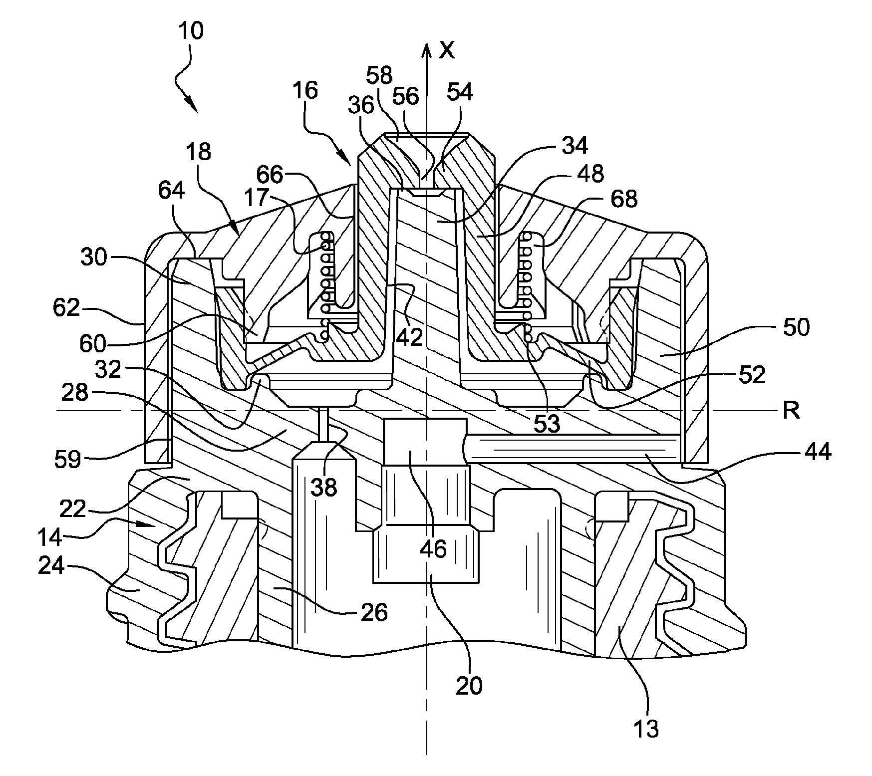
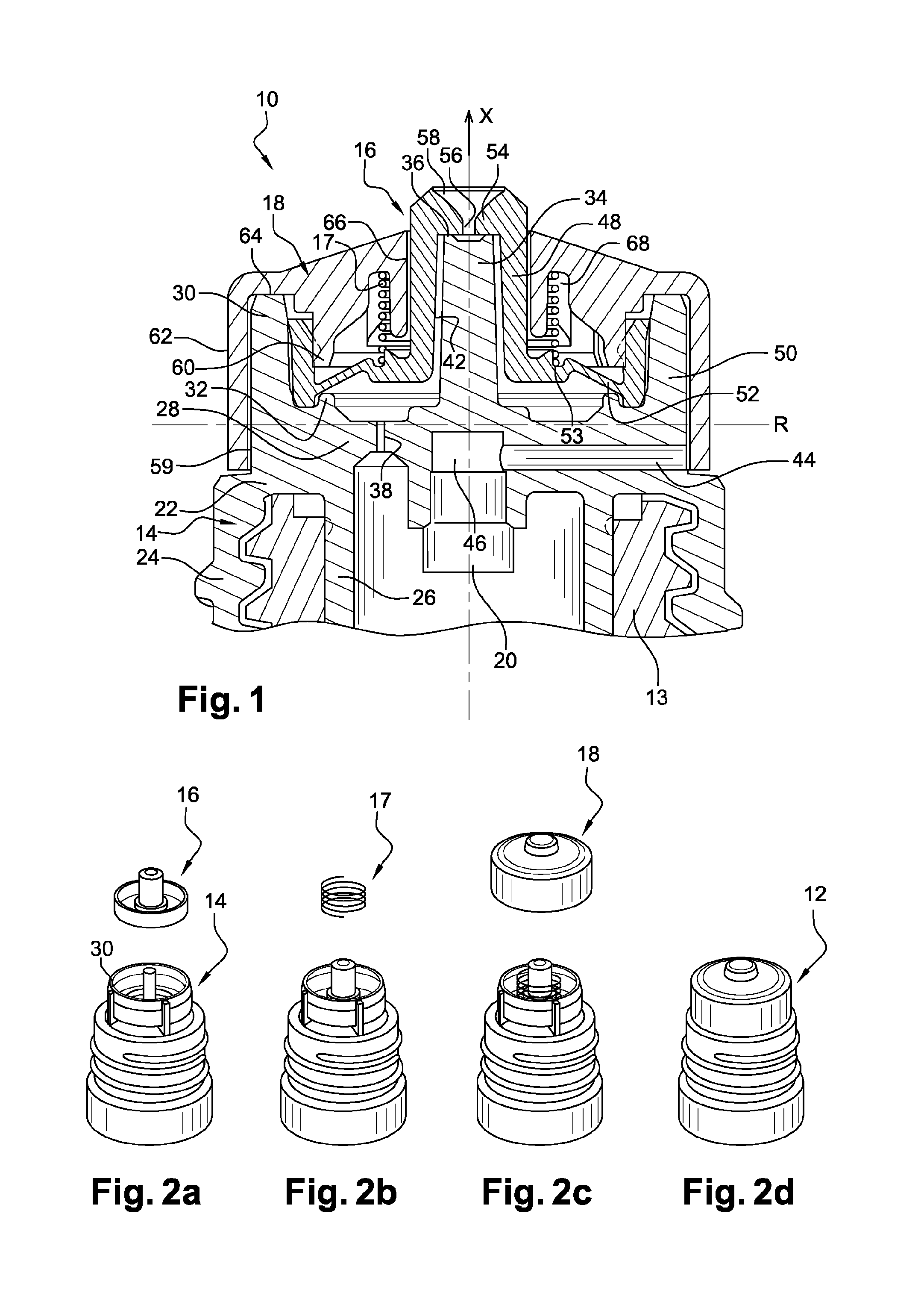
[0036]FIG. 1 shows a device 10 for dispensing liquid in the form of drops. In this example, the dispensed liquid is a pharmaceutical liquid, such as a liquid for forming eyedrops or eardrops. The device 10 comprises a dispenser endpiece 12 screw-fastened on the neck of a container 13. The device 10 is configured so as to dispense liquid as a result of the user squeezing the container 13. In this example, the container is elastically deformable so as to return to its previous shape after being squeezed by a user. The device 10, or at least the container 13, has an axis X of revolution corresponding generally to the liquid ejection direction.

[0037]The endpiece 12 comprises a support 14, a valve 16, a spring 17, a housing 18, and a hydrophobic filter 20.

[0038]In this example, the support 14 comprises a fastener portion 22 disposed at the proximal end of the endpiece for fastening the support on the container 13. This portion 22 comprises an outer skirt 24 tapped so as to be screw-faste...


PUM

PropertyMeasurementUnit
shapeaaaaaaaaaa
pressureaaaaaaaaaa
dimensionsaaaaaaaaaa

Abstract

A liquid dispenser device including a valve with a valve member-forming portion for blocking and passing liquid out from the device, and a fastener edge for permanently fastening the valve relative to a container, the fastener edge including a tubular fastener wall sandwiched between an inner tubular wall and an outer tubular wall.

Description

CROSS-REFERENCE TO RELATED APPLICATIONS[0001]The present application is a continuation of pending International patent application PCT / FR2010 / 051877 filed on Sep. 9, 2010 which designates the United States and claims priority from French patent application 0956278 filed on Sep. 11, 2009, the content of which is incorporated herein by reference.FIELD OF THE INVENTION[0002]The invention relates to the field of dispensing liquid in the form of drops, in particular in the field of pharmaceuticals, e.g. a liquid for eyedrops or eardrops.BACKGROUND OF THE INVENTION[0003]Document U.S. Pat. No. 5,154,325 discloses a liquid dispenser device including an elastomer diaphragm forming a valve member that is disposed between a support and a housing that are mounted on the container. The diaphragm includes a peripheral annular bead and it is held on the device by pinching the bead between the top surface of the support and the bottom surface of the housing. The diaphragm is thus held in the device...

Claims


Application Information

Patent Timeline
Patent Type & Authority Applications(United States)
IPC IPC(8): B65D47/18B23P11/00B65D25/40B67D7/76
CPCB05B11/0021Y10T29/49826B65D47/2081B65D47/2031B05B11/00444
Inventor PAINCHAUD, GAETANGREVIN, GUILLAUMEDECOCK, THIERRYJULIA, XAVIER
Owner NEMERA LA VERPILLIERE SAS
Learn More