
Method and device for producing a component of a turbomachine

a technology of turbomachine and component, which is applied in the direction of arc welding apparatus, metal-working apparatus, welding/cutting media/materials, etc., can solve the problems of lack of deformability, lack of fine-grained component structure, and inability to achieve qualities, etc., to achieve rapid prototyping, increase strength, and rapid manufacturing

Inactive Publication Date: 2012-08-30
MTU AERO ENGINES GMBH
View PDF18 Cites 66 Cited by
  • Summary
  • Abstract
  • Description
  • Claims
  • Application Information

AI Technical Summary

Benefits of technology

[0006]The present invention has the further problem of making a device available for the production of a component of a turbomachine that makes possible the production of components with increased strength, in particular of components of a turbine or of a compressor.
[0009]A method in accordance with the invention for the production of a component of a turbomachine, in particular of a component of a turbine or of a compressor, comprises a generative manufacturing method for the layer-by-layer buildup of the component, whereby after the production of one or several successive component layers a laser-induced or plasma-induced pressure loading of the surface of the last-produced component layer takes place at least partially. As a result of the layer-by-layer strengthening of the component during the generative buildup a strengthening of the entire component takes place. The laser-induced or plasma-induced pressure loading of the surface of the last-produced component layer results in permanent plastic deformations in the structure and in a transformation of the melted structure into a forged structure with a very fine-grained structure. On the whole, a deformation of the melted structure of the component into a forged structure with increased strength results as well as a significant reduction of the microporosity already in the construction phase of the generatively produced component.
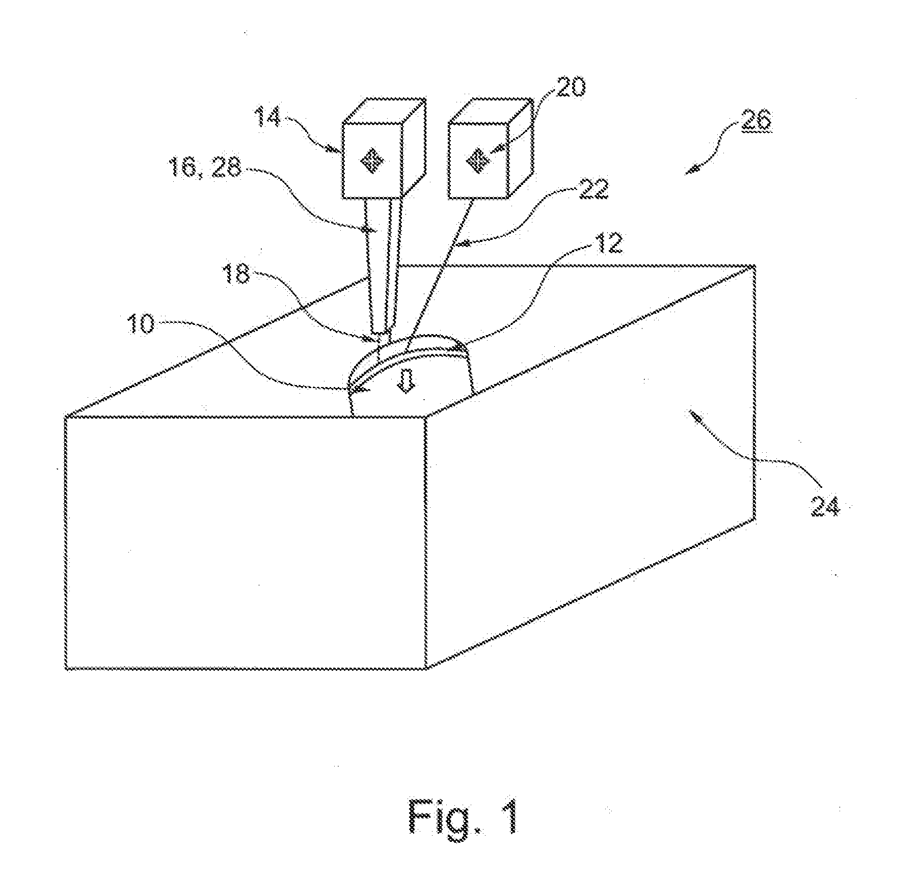
[0014]A device in accordance with the invention for the production of a component of a turbomachine, in particular a component of a turbine or of a compressor, comprises at least one powder supply for applying at least one powdery component material onto a component platform, at least one beam source for a layer-by-layer and local melting or sintering of the component material as well as at least one laser beam source or at least one plasma impulse source for producing a laser-induced or plasma-induced pressure wave. The device in accordance with the invention makes possible the production of components with increased strength since it combines the carrying out of a generative manufacturing method such as, for example, a rapid prototyping method or rapid manufacturing method with the possibility of a laser-induced or plasma-induced pressure loading. The beam source here can be a laser or an electron beam device. The laser is, for example, a CO2— or Nd:YAG laser. The laser beam source for producing the laser-induced pressure loading can be in particular a short pulse laser. The powder supply can be on the one hand an active powder supply that is arranged coaxially or laterally to the beam source for a layer-by-layer and local melting or sintering of the component material or can be a powder bed, whereby the powdery component material is applied layer-by-layer on the powder bed before the melting of sintering. Furthermore, it is possible that the strengthening process takes place parallel to the generative buildup in the same system. The laser beam source and / or the laser for the strengthening of the component and / or of the component layers can, in addition, be used to clean the component surface, so that a subsequent surface finish of the component can be eliminated. To this end only the parameters of the laser, in particular the energy power, have to be adapted. Furthermore, there is the possibility that the laser beam source or the plasma-impulse source is adjusted in such a manner that not only the strengthening step but also the melting and sintering of the component material can be carried out by the laser beam source or the plasma impulse source.

Problems solved by technology

However, this fine-grained component structure has the disadvantage of a lack of deformability, that for example, makes possible an age-hardening and therewith a high strength comparable to a forging alloy.
These qualities can also not be achieved with previous generative methods so that in particular high-temperature components or pressure-loaded components cannot be generatively produced.

Method used


Image

  • Method and device for producing a component of a turbomachine
  • Method and device for producing a component of a turbomachine

Examples


Embodiment Construction

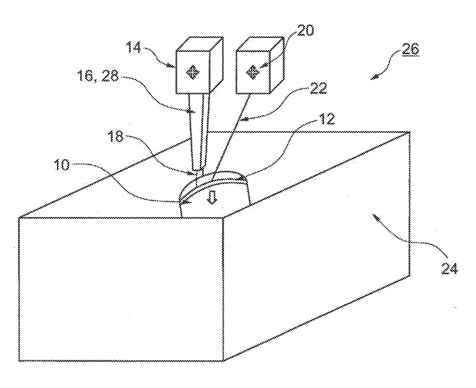
[0018]FIG. 1 shows a schematic representation of the device 26 for the production of the component 10 of a turbomachine. In the exemplary embodiment shown the component 10 is the blade of a high-pressure turbine. The device 26 comprises a beam source 14 for a layer-by-layer and local melting or sintering of a component material 16. The beam source 14 is a pulsed Nd:YAG laser in the example shown. The laser power is ca. 400 to 1000 W as a function of the construction type, in particular the blade type. The average grain size of the powdery component material 16 used is approximately 10 to 100 μm. The component material 16 consists in particular of a titanium alloy or nickel alloy. Moreover, the apparatus 26 comprises a powder supply 28 for applying the powdery component material 16 and comprises a component platform (not shown).

[0019]It can be recognized that in the example shown the powder supply 28 is arranged coaxially to the beam source 14, namely, the laser. The generated laser-...


PUM

PropertyMeasurementUnit
grain sizeaaaaaaaaaa
pressureaaaaaaaaaa
induced pressureaaaaaaaaaa

Abstract

The invention relates to a method for producing a component (10) of a turbomachine, especially a structural part of a turbine or a compressor, the method being a generative production method for the layer-by-layer buildup of the component (10). After production of one or more successive component layers pressure is applied to at least sections of the surface of the most recently produced component layer (12), the pressure being induced by laser or plasma. The invention further relates to a device for producing a component (10) of a turbomachine, especially a structural part of a turbine or a compressor, the device (26) comprising at least one powder feed (28) for the deposition of at least one powder component material (16) onto a component platform, at least one radiation source (14) for a local layer-by-layer fusion or sintering of the component material (16) and at least one laser radiation source (20) or at least one plasma impulse source.

Description

CROSS-REFERENCE TO RELATED APPLICATIONS[0001]This application is a U.S. National Phase application submitted under 35 U.S.C. §371 of Patent Cooperation Treaty application Ser. No. PCT / DE2010 / 001275, filed Oct. 30, 2010, and entitled METHOD AND DEVICE FOR PRODUCING A COMPONENT OF A TURBOMACHINE, which application claims priority to German patent application Ser No. 10 2009 051 551.8, filed Oct. 31, 2009, and entitled VERFAHREN UND VORRICHTUNG ZUR HERSTELLUNG EINES BAUTEILS EINER STRÖMUNGSMASCHINE.[0002]Patent Cooperation Treaty application Ser. No. PCT / DE2010 / 001275, published as WO 2011 / 050790, and German patent application Ser. No. 10 2009 051 551.8, are incorporated herein by reference.TECHNICAL FIELD[0003]The present invention relates to a method for the production of a component of a turbomachine, in particular a component of a turbine or of a compressor, by means of a generative manufacturing process for the layer-by-layer buildup of the component. The invention furthermore rel...

Claims


Application Information

Patent Timeline
Patent Type & Authority Applications(United States)
IPC IPC(8): B23K10/00
CPCB23K26/0069B28B1/001B23K2201/001B22F3/1055B22F5/04B22F2003/1056B22F2999/00B23K26/34C04B2237/341C04B2235/665B23K26/3213B23K26/322B23K26/345B23K35/005B23K35/007B23K35/0244C04B35/645B32B18/00C04B35/16C04B2235/6026B22F2203/13B23K26/32B23K26/342B23K26/356B23K2101/001B23K2103/08B23K2103/14B23K2103/26B23K2103/52Y02P10/25B22F10/28B22F10/50B22F10/36B22F12/43B22F12/41B22F10/364
Inventor BAYER, ERWINHILLER, SVEN-J.
Owner MTU AERO ENGINES GMBH
Learn More