
Method and device for joining components

a technology of components and components, applied in the field of joining components, can solve the problem that the effect of heat can be limited accurately in time, and achieve the effect of rapid, precise and controllable manner

Active Publication Date: 2012-08-23
AIRBUS OPERATIONS GMBH
View PDF9 Cites 22 Cited by
  • Summary
  • Abstract
  • Description
  • Claims
  • Application Information

AI Technical Summary

Benefits of technology

[0007]It is therefore an object of the present invention to make it possible to cure liquid shim in a rapid, precise and controllable manner when joining components.
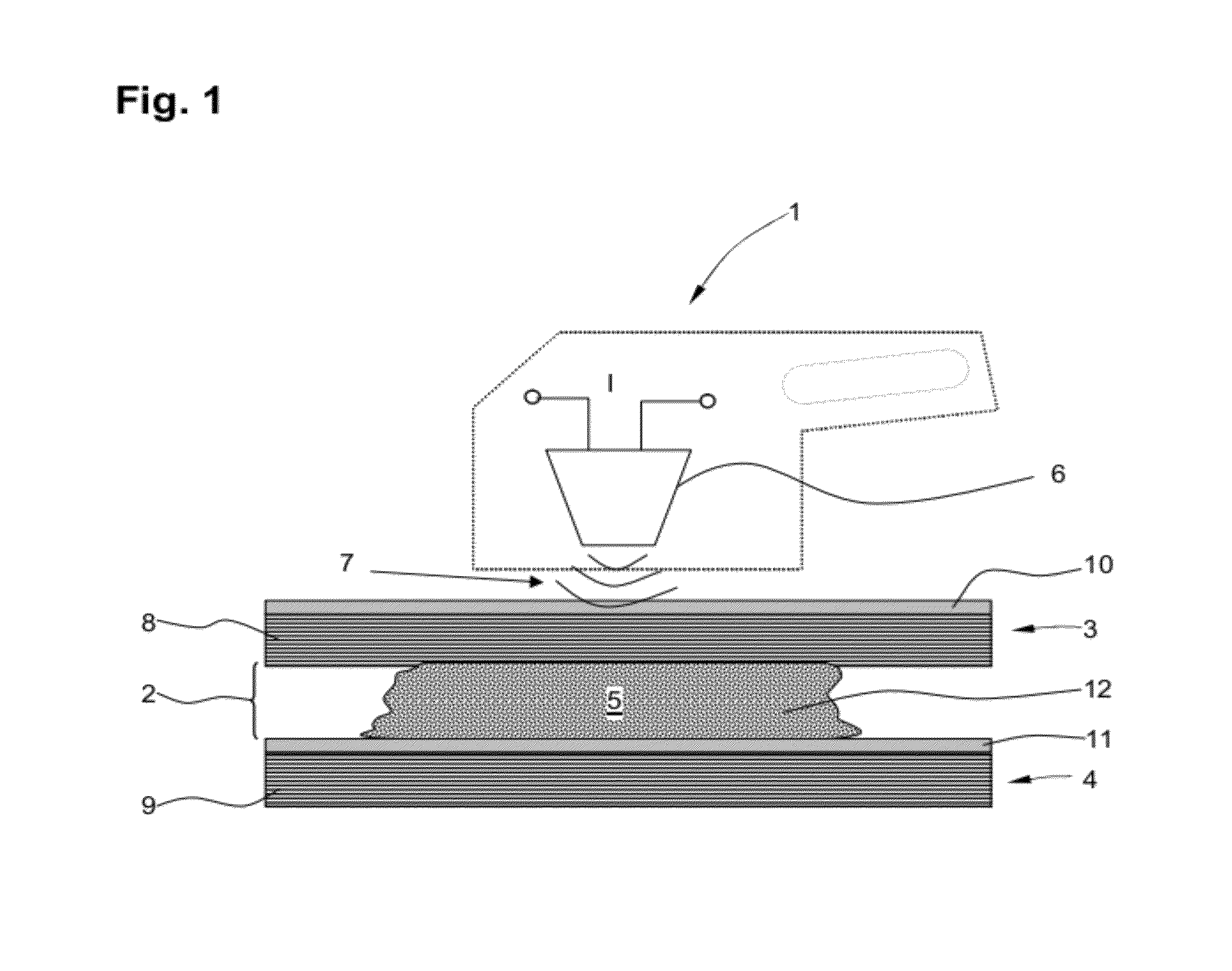
[0009]The small size of the nanoparticles makes it possible to form a particularly stable dispersion with the plastics material filler. Owing to the fact that the energy is introduced locally into the nanoparticles dispersed in the plastics material filler, rapid heating which is limited accurately in space in the gap region between the components to be joined and thus very precise curing of the plastics material filler, for example of a two-component plastics material used, is possible within a short time of less than 30 min. In addition, the effect of heat can be limited accurately in time by controlling the introduction of energy in a suitable manner.
[0014]According to a preferred development, the nanoparticles, the plastics material filler and the type of energy introduced are selected in such a way that—in addition or alternatively to heating—the local introduction of energy stimulates a chemical reaction in the plastics material filler, which reaction is catalysed by the nanoparticles, in order to cure the plastics material filler. In this way, particularly short curing times can be achieved.
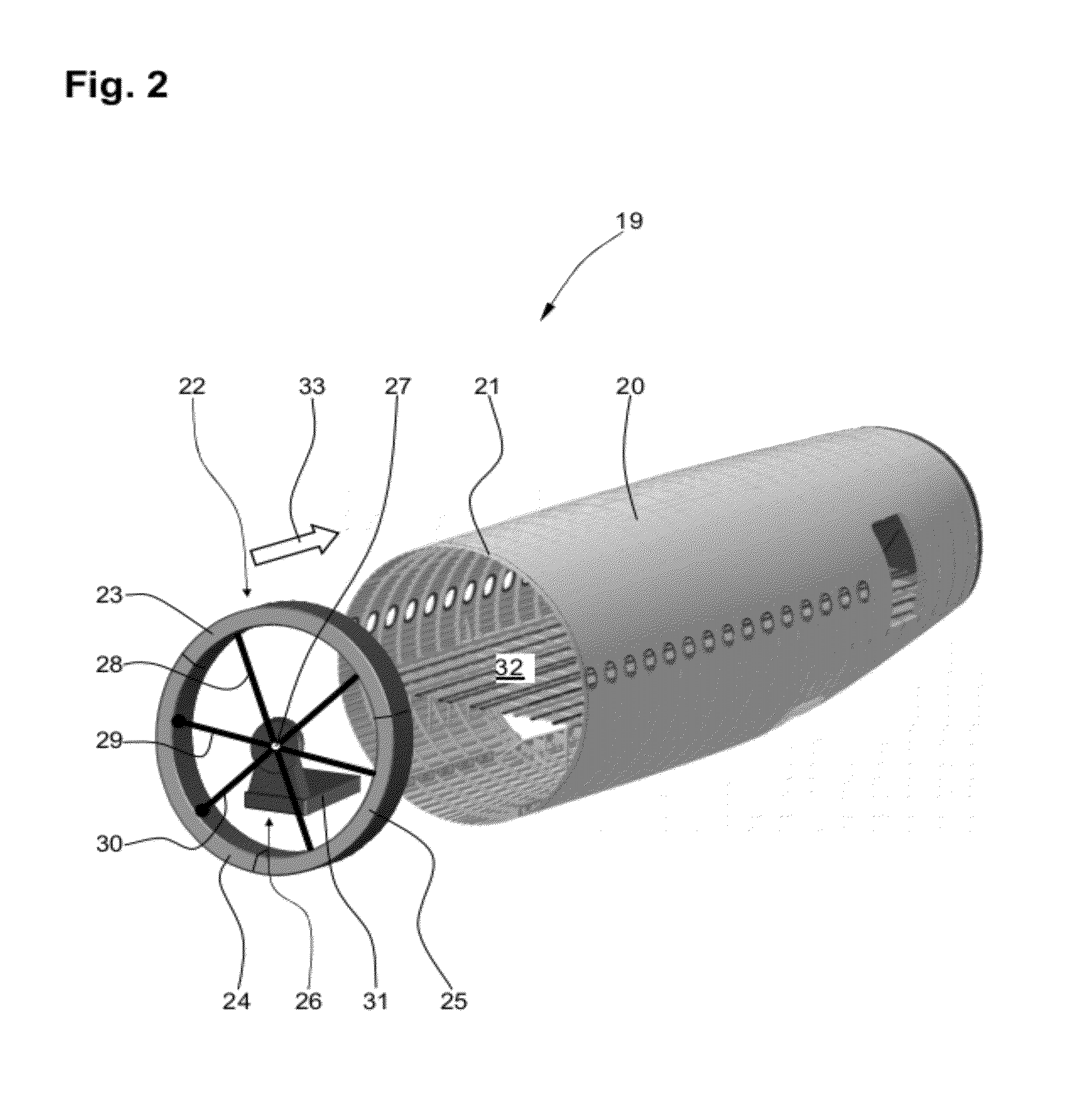
[0018]According to a preferred development, energy is introduced locally through the first and / or second component. In this way, the plastics material filler can be cured even in gaps which are difficult or even impossible to access from the outside.
[0021]According to a preferred development, the nanoparticles comprise a material having a high thermal conductivity which is preferably higher than the thermal conductivity of the plastics material filler. In this way, heat resulting from the local introduction of energy into the nanoparticles reaches the surface of the particles, and thus enters the plastics material filler, particularly quickly.

Problems solved by technology

In addition, the effect of heat can be limited accurately in time by controlling the introduction of energy in a suitable manner.

Method used

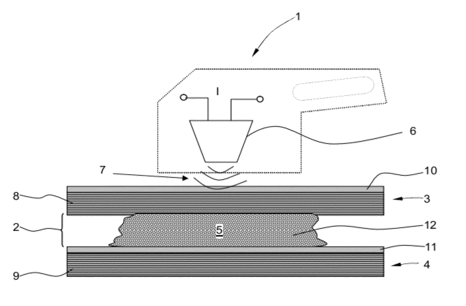

Image

  • Method and device for joining components
  • Method and device for joining components
  • Method and device for joining components

Examples


embodiment 1

[0047]A Method for joining a first and a second component, at least one of which comprises a fibre-reinforced plastics material, comprising the following steps: arranging the components in relation to one another, leaving a gap region between the first and the second component; filling the gap region, at least in portions, with an uncured plastics material filler in which nanoparticles are dispersed; and introducing energy locally into the nanoparticles in order to cure the plastics material filler.

embodiment 2

[0048]The method according to embodiment 1, wherein the gap region has a width of from 0.3 mm to 2 mm.

embodiment 3

[0049]The method according to either embodiment 1 or embodiment 2, wherein a step of heating the plastics material filler by the local introduction of energy, in particular to between 40° C. and 90° C., in order to cure the plastics material filler is provided.


PUM

PropertyMeasurementUnit
widthaaaaaaaaaa
diameteraaaaaaaaaa
timeaaaaaaaaaa

Abstract

A method for joining a first and a second component, at least one of which comprises a fibre-reinforced plastics material. The components are arranged in relation to one another in such a way that a gap region remains between the first and the second component. The gap region is filled, at least in portions, with an uncured plastics material filler in which nanoparticles are dispersed. Energy is introduced locally into the nanoparticles in order to cure the plastics material filler. In another aspect, the invention provides a device for joining two components.

Description

CROSS-REFERENCE TO RELATED APPLICATIONS[0001]This application is a continuation of and claims priority to PCT / EP2010 / 061076 filed Jul. 30, 2010, which claims the benefit of and priority to U.S. Provisional Application No. 61 / 234,780, filed Aug. 18, 2009 and German Patent Application No. 10 2009 028 613.6 filed Aug. 18, 2009, the entire disclosures of which are herein incorporated by reference.FIELD OF THE INVENTION[0002]The present invention relates to a method for joining components, at least one of which comprises a fibre-reinforced plastics material. The invention also relates to a device for joining components.[0003]Although the present invention and the problem on which is it based can be applied to any components, they will be described in detail with reference to fuselage shell components of an aircraft.[0004]Fibre-reinforced composite materials, for example carbon-fibre-reinforced epoxy resins, are increasingly being used in modern aircraft construction. Fuselage sections fo...

Claims


Application Information

Patent Timeline
Patent Type & Authority Applications(United States)
IPC IPC(8): B32B37/00
CPCB29C35/02B29C65/4875B29C65/08B29C65/14B29C65/1409B29C65/1412B29C65/1425B29C65/1467B29C65/4835B29C65/485B29C65/4855B29C66/1122B29C66/612B29C66/721B29C66/861B29C66/919B29C2035/0811B29C2035/0822B29C2035/0855B29K2063/00B29K2105/06B29K2305/10B29K2307/00B29K2995/0005B29K2995/0013B29L2009/003B29L2031/3082B64F5/0009C08J5/121C09J5/00C09J5/06C09J2201/602C09J2205/31C09J2400/22C09J2400/226B29C35/0261B29C65/4885B29C65/489B29C66/545B29C66/91655B29C66/91411B29C65/1435B29C65/3612B29C65/3656B29C65/3668B29C65/368B29C66/7212B29C66/723B29C66/72321B29C66/91651B29C65/00B29K2307/04B29C66/71B64F5/10B29K2105/162C09J2301/314C09J2301/416
Inventor LITZENBERGER, KARSTENEDELMANN, KLAUSSCHWEIM, MATTHIASSCHILDT, RAINER
Owner AIRBUS OPERATIONS GMBH
Learn More