
Cam cover coil on plug retention via oil separator

a technology of oil separator and cam cover, which is applied in the direction of electric ignition installation, mechanical equipment, machines/engines, etc., can solve the problems of significant expansion of the oil separator and thus of the cam cover, and achieve the effects of reducing engine emissions, reducing costs, and reducing oil induction

Inactive Publication Date: 2012-08-16
FORD GLOBAL TECH LLC
View PDF16 Cites 2 Cited by
  • Summary
  • Abstract
  • Description
  • Claims
  • Application Information

AI Technical Summary

Benefits of technology

[0003]Engines may utilize positive crankcase ventilation (PCV) systems to reduce engine emissions. Specifically, pressurized gasses from the engine's crankcase may contain various hydrocarbons. By routing the pressurized gasses back to the engine intake, the gasses can be inducted into the engine cylinder, thus burning the hydrocarbons in the cylinder. However, oil may be entrained in the pressurized gasses, and thus oil separators may be used on the intake side of the PCV system to reduce oil inducted in the intake system. Such oil separators may be integrated into the engine cam cover to reduce costs.
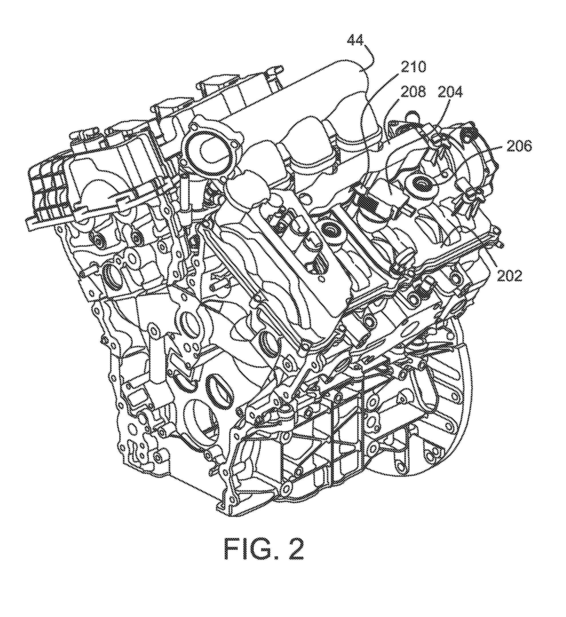
[0004]In some engines, the effectiveness and degree of oil separation required in some engines can cause the size of the oil separator, and thus portions of the cam cover, to grow significantly. Such increased size can sometimes have degrading secondary effects on various components, such as coil-on-plug assemblies coupled to the engine's spark plugs.
[0007]In this way, the increased size of the oil separator can be configured to provide the COP retention, rather than simply taking up more under-hood packaging space. For example, by extending the ball out of the cam cover's oil separator using retention arms and ribs, the COP assembly can utilize the oil separator structure to support retention of the COPs.
[0008]Furthermore, in some examples, specially designed inserts typically are included in the cam cover to house and / or receive a fastener. Use of the ball lock assembly as described may eliminate use of the fastener, if desired. Thus, by utilizing a ball and socket retention system, a lower cost connection with reduced assembly time can be achieved.

Problems solved by technology

In some engines, the effectiveness and degree of oil separation required in some engines can cause the size of the oil separator, and thus portions of the cam cover, to grow significantly.

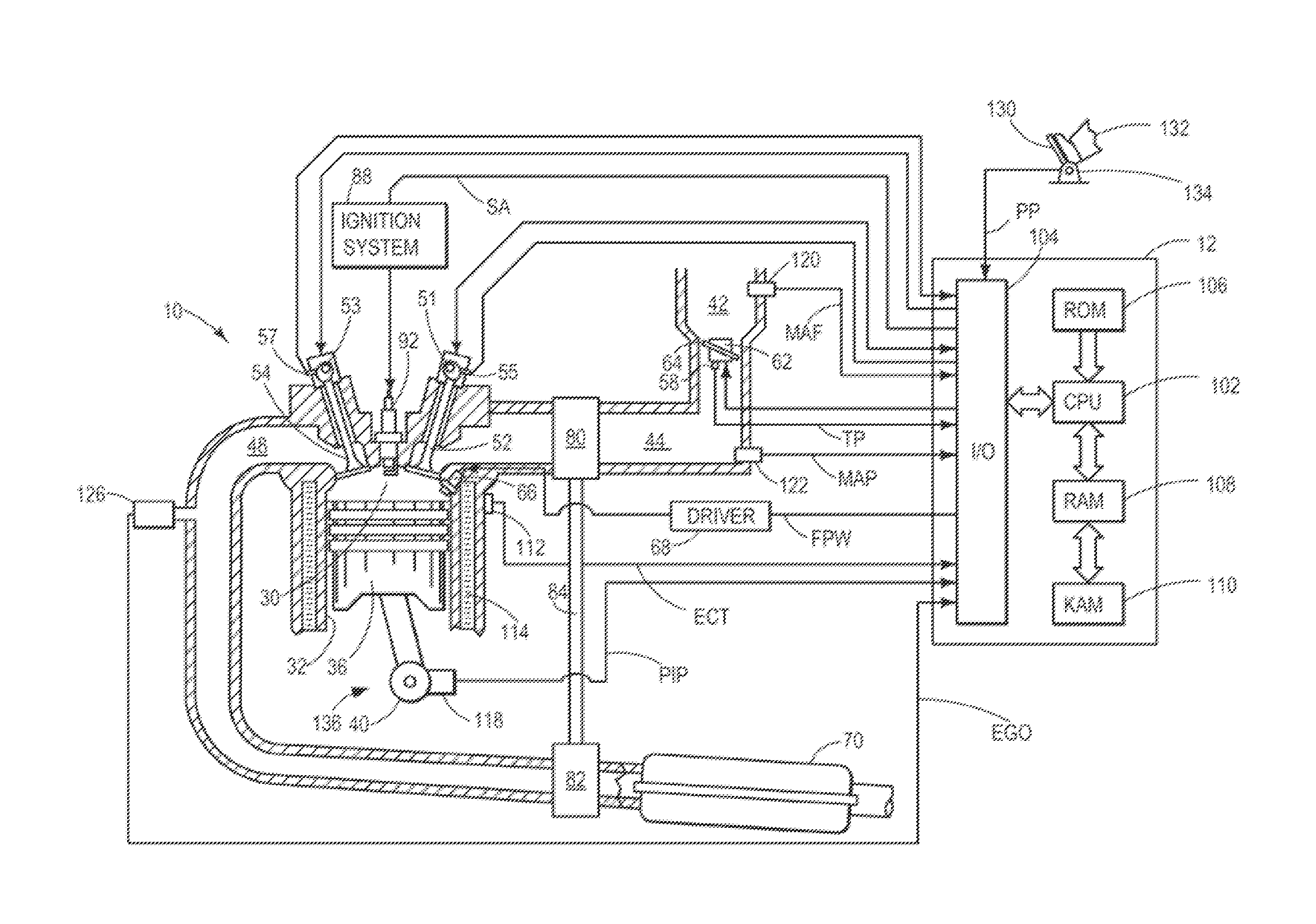
Method used


Image

  • Cam cover coil on plug retention via oil separator
  • Cam cover coil on plug retention via oil separator
  • Cam cover coil on plug retention via oil separator

Examples


Embodiment Construction

[0018]Embodiments of an oil separator coil-on-plug (COP) retention feature are disclosed herein. Such a retention feature may use the oil separator structural configurations to enable a ball and socket joint to attach a COP to a cam cover, as described in more detail hereafter.

[0019]Referring to FIG. 1, internal combustion engine 10, comprising a plurality of cylinders, one cylinder of which is shown in FIG. 1, is controlled by electronic engine controller 12. Engine 10 includes combustion chamber 30 and cylinder walls 32 with piston 36 positioned therein and connected to crankshaft 40. Combustion chamber 30 is shown communicating with intake manifold 44 and exhaust manifold 48 via respective intake valve 52 and exhaust valve 54. Each intake and exhaust valve may be operated by an intake cam 51 and an exhaust cam 53. Alternatively, one or more of the intake and exhaust valves may be operated by an electromechanically controlled valve coil and armature assembly. The position of intak...


PUM


Abstract

A system for a cylinder head is provided. The system comprises a cam cover mounted on the cylinder head and including an oil separator and a coil on plug (COP) coupled to the oil separator via a snap-fit connection. The snap-fit connection holds the coil-on-plug in position and may provide a lower cost alternative to existing systems of retaining coil-on-plugs on a cam cover.

Description

RELATED APPLICATIONS[0001]The present application claims priority to U.S. Provisional Application No. 61 / 443,609 filed on Feb. 16, 2011, and U.S. Provisional Application No. 61 / 444,392 filed on Feb. 18, 2011, the entire contents of each of which are hereby incorporated by reference for all purposes.FIELD[0002]The present disclosure relates to a positive crankcase ventilation system for an engine.BACKGROUND AND SUMMARY[0003]Engines may utilize positive crankcase ventilation (PCV) systems to reduce engine emissions. Specifically, pressurized gasses from the engine's crankcase may contain various hydrocarbons. By routing the pressurized gasses back to the engine intake, the gasses can be inducted into the engine cylinder, thus burning the hydrocarbons in the cylinder. However, oil may be entrained in the pressurized gasses, and thus oil separators may be used on the intake side of the PCV system to reduce oil inducted in the intake system. Such oil separators may be integrated into the...

Claims


Application Information

Patent Timeline
Patent Type & Authority Applications(United States)
IPC IPC(8): F02P3/02
CPCF01M13/0416H01F38/12F02P13/00F02P3/02
Inventor VALENCIA, FRANK ACIERNO
Owner FORD GLOBAL TECH LLC
Learn More