Method of operating polymer electrolyte fuel cell

a fuel cell and electrolyte technology, applied in the direction of solid electrolyte fuel cells, fuel cells, cell components, etc., can solve the problems of inability to form a char layer under the above conditions, small improvement of output density, and unclear effectiveness of rod-shaped minute protrusions, etc., to achieve high electric power generation performance, performance deterioration, and surface area increase

Inactive Publication Date: 2012-07-26
PANASONIC CORP
View PDF4 Cites 0 Cited by
  • Summary
  • Abstract
  • Description
  • Claims
  • Application Information

AI Technical Summary

Benefits of technology

[0020]The above-described patent and non patent literature describe that the cell performance improvement effect by the formation of the projections and depressions on the surface of the membrane is obtained by, as a primary factor, the increase in the contact area between the electrolyte membrane and the catalyst layer and by, as a secondary factor, the proton bypass transport effect. As a result, the structures for increasing the surface area of the electrolyte membrane have been proposed regardless of the thickness of the catalyst layer. However, the present inventors have succeeded in obtaining data indicating that the proton bypass transport effect on the cathode side is the primary factor of the cell performance improvement. Based on this data, the configuration in which the height of the projection or the depth of the depression on the cathode-side surface of the electrolyte membrane is large, and the thickness of the catalyst layer on the cathode side is small is adopted such that the protons from the electrolyte membrane are easily supplied to portions of the catalyst layer, the portions being located far away from the electrolyte membrane and close to the gas diffusion layer.
[0021]However, according to this configuration, although the supply of the protons to the catalyst layer becomes easy, it becomes difficult to discharge the moisture generated by an electric reaction at the catalyst layer contacting the depressions of the electrolyte membrane (to be specific, at a deepest portion of the catalyst layer). The reactant gases are generally humidified such that the high electric power generation performance is obtained by the flat electrolyte membrane. In a case where the fuel cell is operated by supplying the humidified reactant gases to the electrolyte membrane including the depression-projection structure, the generated water condenses at the deepest portion of the catalyst layer and accumulates. Thus, the performance deteriorates with time during the electric power generation. The performance deterioration due to the accumulation of the water becomes significant during the operation at high current density. Therefore, according to the fuel cell in which the height of the projection or the depth of the depression on the cathode-side surface of the electrolyte membrane is large and the thickness of the catalyst layer on the cathode side is thin, by setting the relative humidity of the oxygen-containing gas supplied to the cathode side to 10% or less, the generated water or the condensed water does not accumulate, and the higher performance than before can be continuously achieved.

Problems solved by technology

However, it is considered that the char layer cannot be formed under the above conditions.
Therefore, Japanese Laid-Open Patent Application Publication No. 2005-108822 does not disclose a feasible manufacturing method.
In addition, since specific or quantitative explanations regarding results of a performance evaluation are not disclosed at all, the effectiveness of the rod-shaped minute protrusion is unclear.
However, the improvement of the output density is small, that is, twice at most.
Further, electric power generation conditions, especially a humidification condition of a supply gas, are not adequately disclosed.
However, J. Am. Chem. Soc., Vol. 128, No. 39, 12971 (2006) does not disclose the desirable shape of the minute structure on the surface of the electrolyte membrane and the humidification condition of the supply gas.
In addition, the degree of improvement of the output density disclosed in each literature is low, and a large effect which can change the practical value of the fuel cell is not achieved.

Method used


Image

  • Method of operating polymer electrolyte fuel cell
  • Method of operating polymer electrolyte fuel cell
  • Method of operating polymer electrolyte fuel cell

Examples


embodiment 1

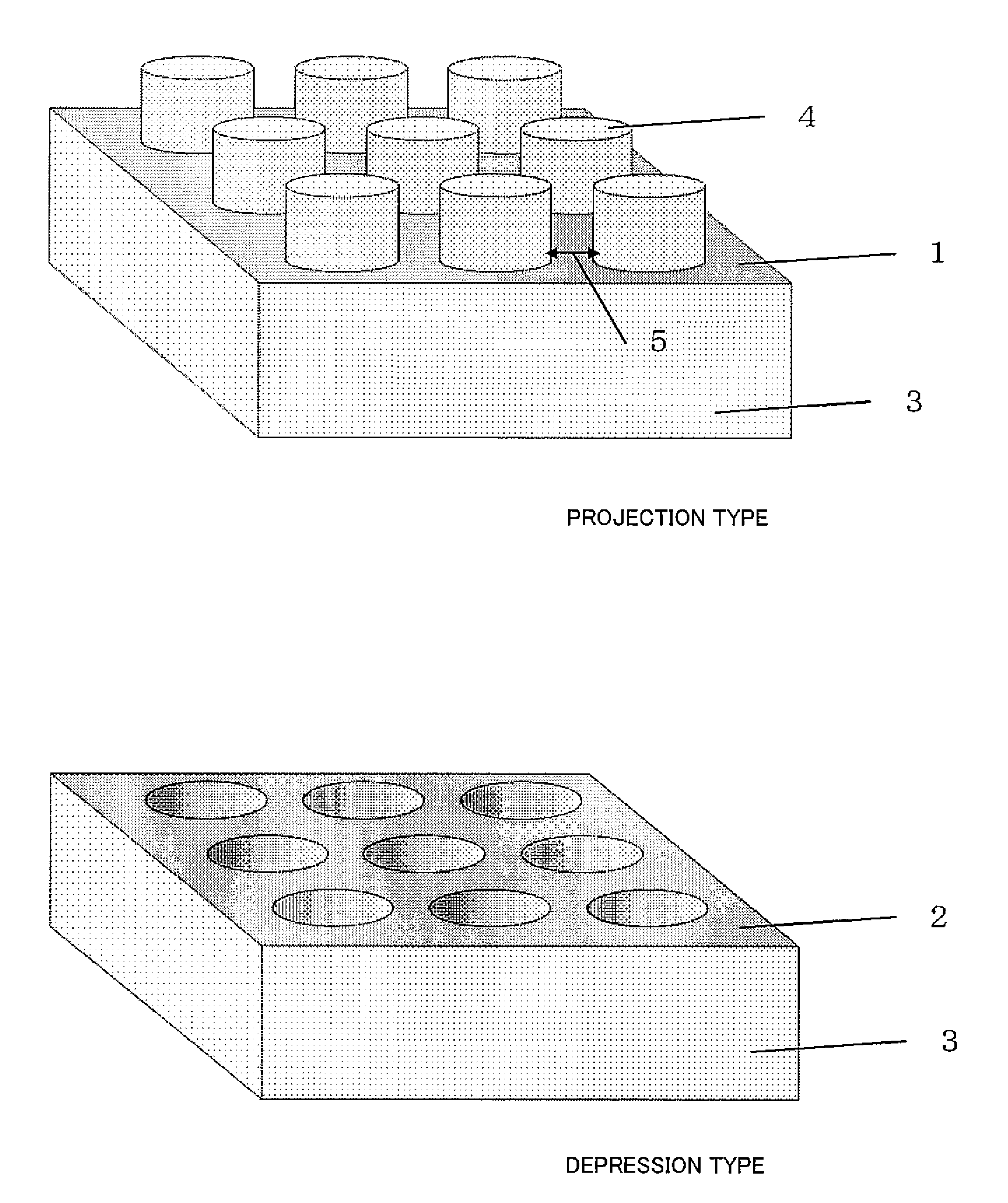
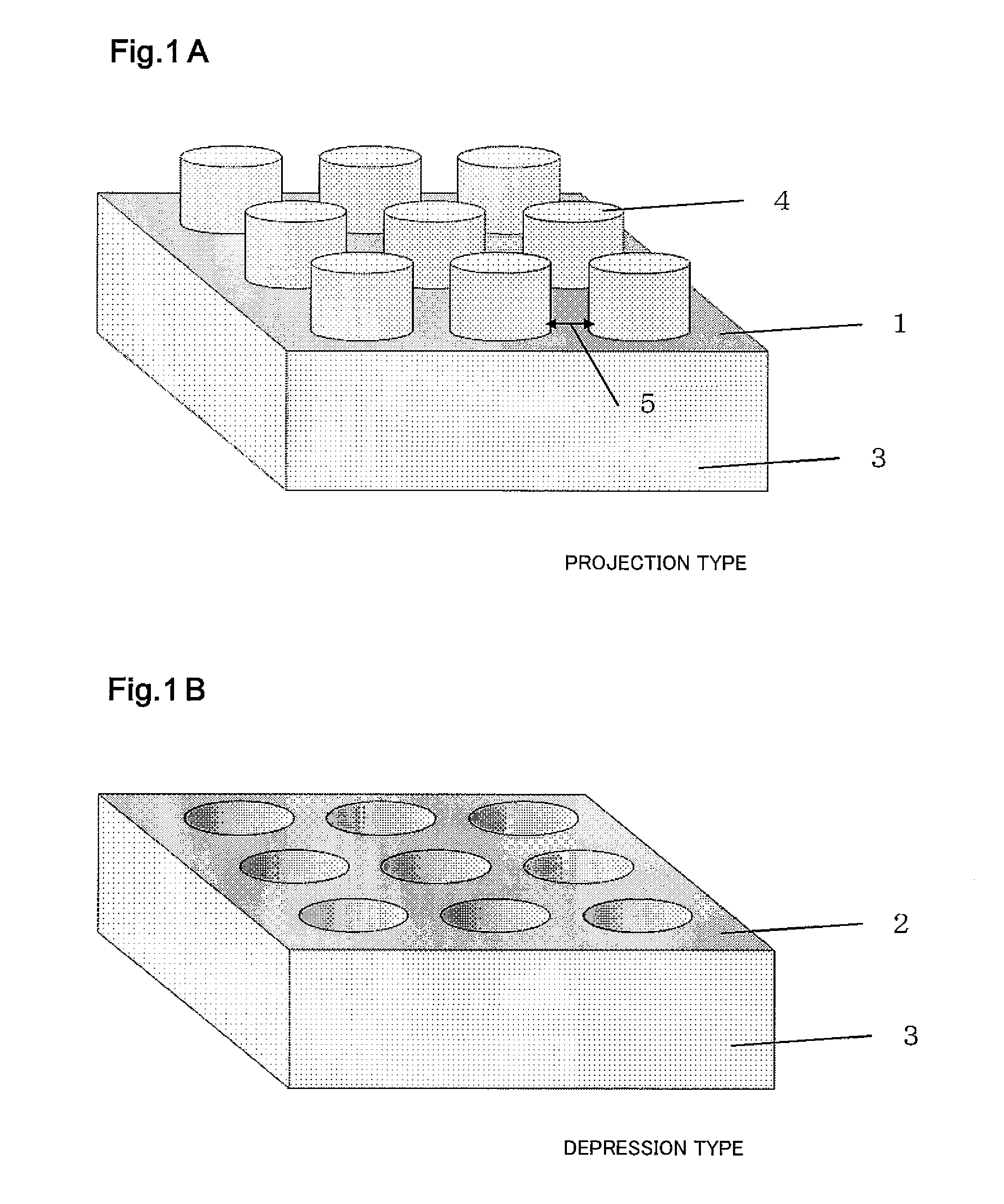
[0032]FIGS. 1A and 1B are conceptual diagrams each showing the surface of an electrolyte membrane including a depression-projection structure in the present invention. As shown in FIG. 1A, a structure in which a flat lower base portion 1 is continuously formed and a plurality of discontinuous protrusions (projections) are formed on the flat lower base portion 1 is called a projection type in the present invention. As shown in FIG. 1B, a structure in which a flat upper base portion 2 is continuously formed and a plurality of discontinuous holes (depressions) are formed on the flat upper base portion 2 is called a depression type in the present invention. FIGS. 1A and 1B show columnar projections and depressions as a representative example. However, the shape of each of the projections and depressions may be a polygonal column, such as a quadrangular prism or a triangular prism. In addition, the shape may be a cone or a pyramid. Various shapes are applicable to the projections and dep...

example 1

[0045]A projection type electrolyte membrane was produced by the casting of a fluoropolymer electrolyte solution by using a depression type mold. The depression type mold was produced by: forming various patterns on a silicon wafer by masks; and performing plasma etching. The cross-sectional shape of the projection and the projection-projection interval were adjusted by a mask pattern, and the height of the projection was adjusted by the time and intensity of the plasma etching. Used as the polymer electrolyte solution was a Nafion liquid (water / alcohol solvent, solid content ratio was adjusted to about 20%). The silicon wafer on which the projections of various shapes and the depressions of various shapes were formed was coated with the Nafion liquid and was then dried. When drying, the temperature and humidification conditions of the atmosphere were adjusted. According to need, the Nafion liquid coating and the drying were repeatedly performed plural times. After the drying, a hea...

example 2

[0063]In Example 1, the current-voltage characteristics of the small cells each including the projection type electrolyte membrane were evaluated. In Example 2, the current-voltage characteristics of the small cells each including the depression type electrolyte membrane were evaluated. In this depression type electrolyte membrane, the diameter of the depression was set to 10 μm. A depression-depression interval, that is, a rib width was set to 5 μm that was the same as the diameter (φ) of the projection of the projection type membrane, and the depth of the depression was set to 10 or 15 μm that was the same as the height of the projection of the projection type membrane. The other components, such as the catalyst layer and the gas diffusion layer, were the same as those of the small cell including the projection type membrane in Example 1. Thus, the small cell was produced, and the current-voltage characteristics thereof were evaluated.

[0064]FIG. 7 shows the current-voltage charact...


PUM

PropertyMeasurementUnit
depthaaaaaaaaaa
heightaaaaaaaaaa
thicknessaaaaaaaaaa

Abstract

A polymer electrolyte fuel cell includes a cathode, an anode, and an electrolyte membrane sandwiched between the cathode and the anode. A plurality of projections each having a height of 5 to 15 μm or a plurality of depressions each having a depth of 5 to 15 μm are formed on a surface of the electrolyte membrane, the surface being opposed to the cathode. The cathode is constituted by a catalyst layer formed to tightly contact the surface of the electrolyte membrane and having a maximum thickness that is one to three times the height of the projection or the depth of the depression. An oxygen-containing gas having a relative humidity of 10% or less is supplied to the cathode, and electric power is generated by using the polymer electrolyte fuel cell.

Description

[0001]This is a continuation application under 35 U.S.C 111(a) of pending prior International application No. PCT / JP2010 / 003930, filed on Jun. 14, 2010.BACKGROUND OF THE INVENTION[0002]1. Field of the Invention[0003]The present invention relates to an electric power generating method of a polymer electrolyte fuel cell which can be used as an electric car power supply or a domestic power supply system and uses hydrogen or hydrocarbon, such as alcohol, as fuel.[0004]2. Description of the Related Art[0005]To improve the performance of a polymer electrolyte fuel cell, a method has been reported, in which: projections and depressions are formed on the surface of an electrolyte membrane to increase a contact area between a catalyst layer and the electrolyte membrane. Japanese Laid-Open Patent Application Publication No. 2005-108822 discloses a method in which a projection-depression structure is formed on the surface of the electrolyte membrane by pressing against the surface of the elect...

Claims


Application Information

Patent Timeline
Patent Type & Authority Applications(United States)
IPC IPC(8): H01M8/06H01M8/10H01M4/86
CPCH01M4/8642H01M8/04089Y02E60/521H01M8/04835H01M8/1006H01M8/04119Y02E60/50
Inventor GYOTEN, HISAAKIAIZAWA, MASATOTAOMOTO, AKIRA
Owner PANASONIC CORP
Why Eureka
Try Eureka