
High thermal conductance thermal interface materials based on nanostructured metallic network-polymer composites

a composite material and high thermal conductivity technology, applied in the direction of coatings, material nanotechnology, chemistry apparatus and processes, etc., can solve the problems of reduced conductivity of composite structures, undesirable increase in thermal resistance, and increase in bond line thickness (blt) of composite structures, so as to promote wetting and dispersion of nanoparticles, high thermal conductivity, and low filler loading and viscosity

Inactive Publication Date: 2012-07-26
IBM CORP +1
View PDF3 Cites 32 Cited by
  • Summary
  • Abstract
  • Description
  • Claims
  • Application Information

AI Technical Summary

Benefits of technology

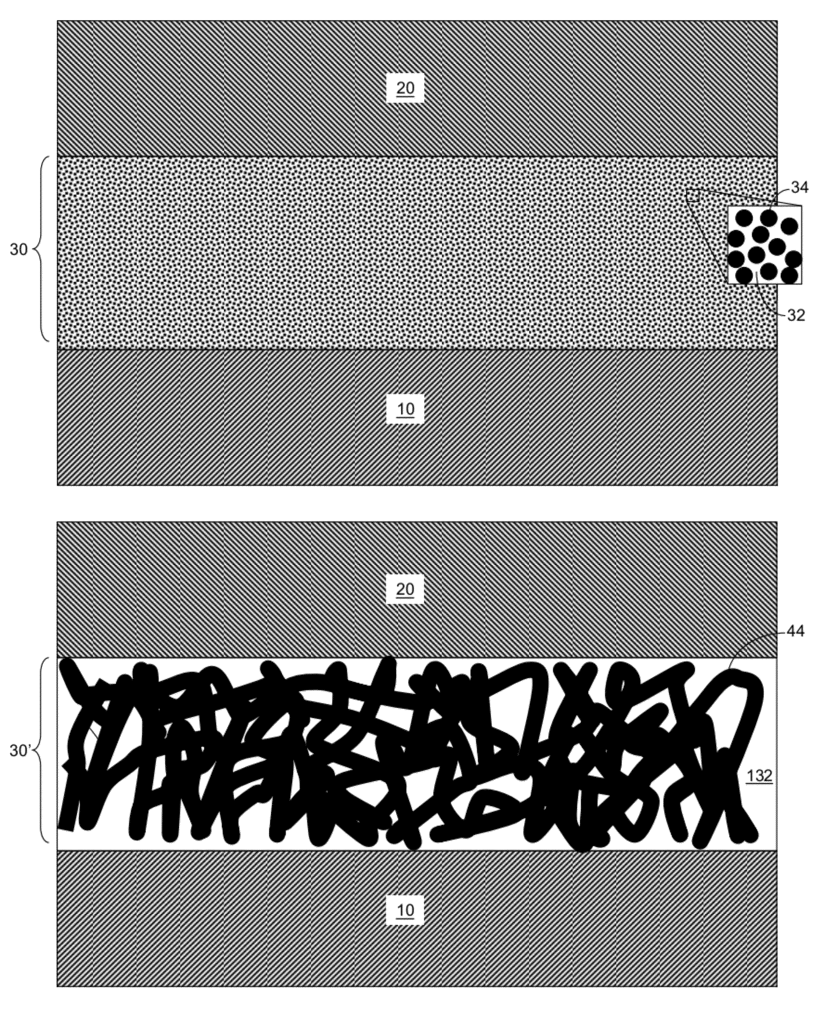
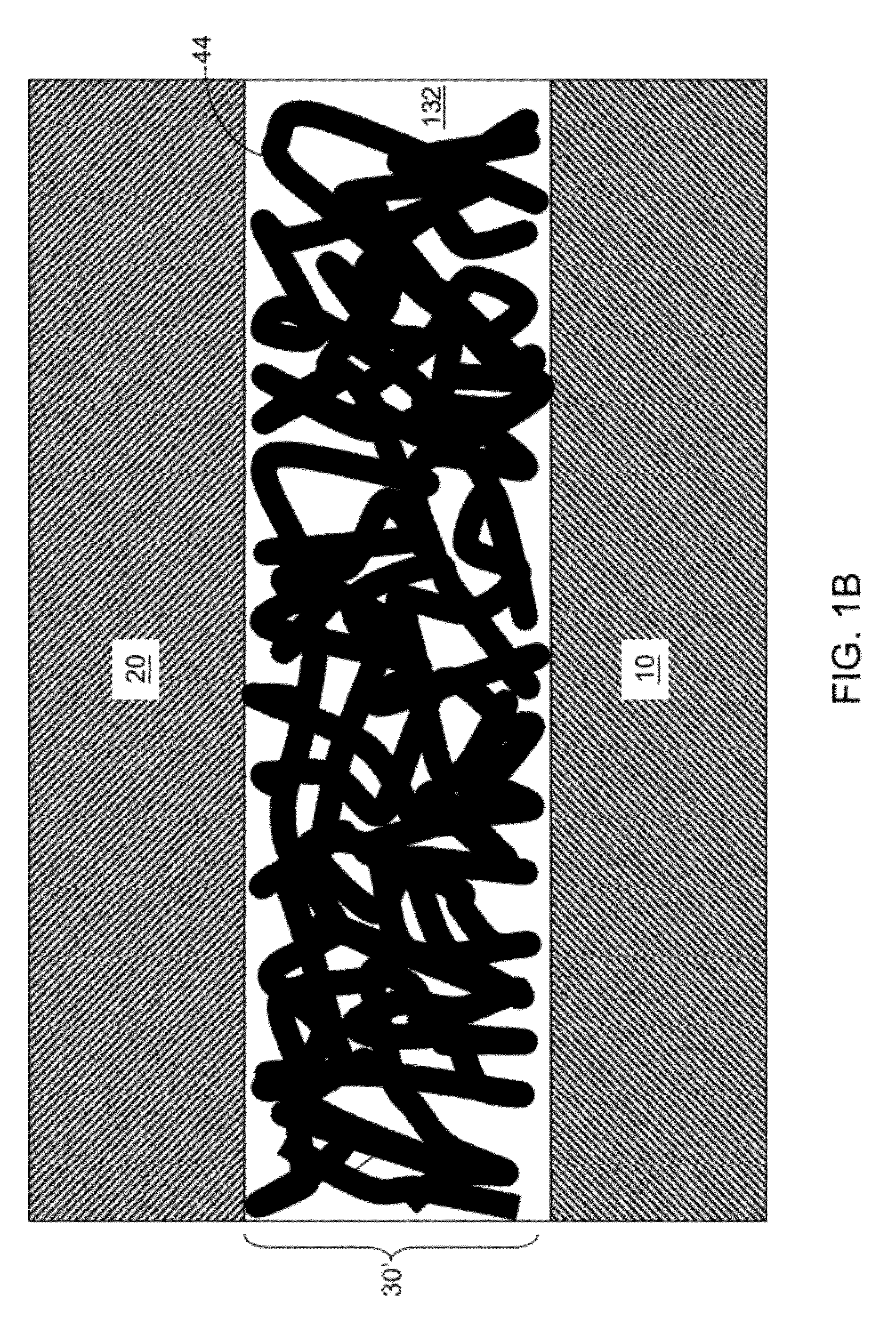
[0013]A composite structure provides high thermal conductivity with a relatively low filler loading and viscosity. The composite structure is formed by dispersing nanoparticles in a matrix at a low filler loading, and controlled sintering of the composite structure to induce agglomeration of the nanoparticles into a connected percolating thermally conducting network structure within the matrix.
[0014]The nanoparticles can be coated to promote wetting and dispersion of the nanoparticles in the matrix. The coating can be removed at relatively low temperatures before sintering and matrix curing occurs. The melting temperature of the nanoparticles is reduced due to small size, thereby enabling a low temperature sintering. An interconnected, high-thermal-conductivity network is formed inside the matrix during the sintering process.

Problems solved by technology

The associated increase in stiffness, i.e., an increase in the viscosity or compressibility, introduces challenges in manufacturing processes (dispense and handling) and product applications (stresses on fragile components, or accommodating stack-up tolerances).
Decreasing the particle size typically results in reduction of the conductivity of the composite structure.
While increasing the particle size above 10 microns can increase the conductivity of the composite structure, such large particles and / or increased filler loadings result in dilatant behavior in grease type TIMs and / or an increase in the Bond Line Thickness (BLT) of the composite structure, and therefore, an undesirable increase in thermal resistance, i.e., an undesirable decrease in thermal conductance of the composite structure.
A vital problem of all PCM based thermal energy storage systems is the low thermal conductivity (κ) of the PCM, which restricts the heat transfer rate as well as the fast access to the thermal energy stored away from the heat transfer surfaces.
In addition, most available commercial PCMs are corrosive to most metals and suffer from decomposition, high changes in volume during phase change, and flammability that can affect phase change properties.
These disadvantages keep conventional PCMs from large scale implementations.
The associated increase in viscosity or stiffness / compressibility introduces challenges in manufacturing processes (dispense and handling) and product applications (stresses on fragile components or accommodating stackup tolerances).
Thermal greases are limited by pump-out resulting from an expansion and contraction at the thermal interfaces.
This pumping effect can push the material away from the interface and cause a hot spot.
Poor wetting of the surface, low yield strength and melting point and environmental health concern and package stresses make solder systems an inconvenient material for TIM.
Usage of liquid metals between the mating surfaces may also cause corrosion damage.
However the high sintering temperature (˜300° C.) of the commercial silver pastes makes such pastes an impractical thermal interface material.

Method used


Image

  • High thermal conductance thermal interface materials based on nanostructured metallic network-polymer composites
  • High thermal conductance thermal interface materials based on nanostructured metallic network-polymer composites
  • High thermal conductance thermal interface materials based on nanostructured metallic network-polymer composites

Examples


examples

[0080]A high thermal conductivity nanocomposite was obtained at relatively low filler loading by controllably producing the highly connected, metallic network in an epoxy matrix. Pure epoxies have low κ of about 0.18 W / mK.

[0081]Following the steps of FIGS. 5A-5C, a high thermal conductivity network (HTCN) was formed after dispersion and controlled sintering of silver nanoparticles. Thermal conductivity measurements showed a thermal conductivity of about 29 W / mK, for 20 nm silver nanoparticles based composites with a volume fraction of 30%. Even at lower nanoparticle volume fractions (10%), the measured thermal conductivities in the nanocomposites was about 7 W / mK. which surpasses the thermal conductivity reported for epoxy microparticle composites as known in the art.

[0082]Moreover, a fundamental difference between the microparticle and the nanoparticle based composites has been observed. At the same volume fractions, silver-epoxy based composited obtained with 2˜4 μm diameter silve...


PUM

PropertyMeasurementUnit
volume fractionaaaaaaaaaa
temperatureaaaaaaaaaa

Abstract

A composite structure provides high thermal conductivity as a thermal interface structure with a relatively low filler loading. The composite structure is formed by dispersing nanoparticles in a matrix at a low filler loading, and controlled sintering of the composite structure to induce agglomeration of the nanoparticles into a connected percolating thermally conducting network structure within the matrix.

Description

CLAIM OF PRIORITY[0001]This application is based on, and claims the benefit of priority from, U.S. Provisional Patent Application 61 / 435,854 filed on Jan. 25, 2011.BACKGROUND[0002]The present disclosure relates to a high thermal conductivity composite structure, and specifically to a composite structure having a connected percolating thermally conducting network structure comprising a thermal interface material (TIM), and methods of manufacturing the same.[0003]Thermal interface material (TIM) is a material used to minimize the contact thermal resistance between surfaces and provides a low resistance path to spread and remove heat. Examples of TIM known in the art employ randomly distributed filler materials dispersed in a matrix. Each of the randomly distributed filler materials has a characteristic dimension (such as a diameter) on the order of several microns or greater.[0004]In such conventional dispersed systems, the filler loading needs to be at least 50˜60% in order to achiev...

Claims


Application Information

Patent Timeline
Patent Type & Authority Applications(United States)
IPC IPC(8): C09K5/06C09K5/14B82Y30/00B82Y40/00
CPCB82Y30/00C09K5/14C09K5/063C08K3/08C08K2003/0806C08L63/00C09D139/06
Inventor IRUVANTI, SUSHUMNABORCA-TASCIUC, THEODORIANRAEISI-FARD, HAFEZLAI, FENGYUANPASHAYI, KAMYARPLAWSKY, JOEL
Owner IBM CORP
Learn More