
Vehicle control system

a control system and vehicle technology, applied in the direction of electric control, machines/engines, mechanical equipment, etc., can solve the problems of friction loss, engine pumping loss, and shocks that may occur in the continuously variable transmission, and achieve the effect of reducing shocks

Active Publication Date: 2012-07-19
TOYOTA JIDOSHA KK
View PDF2 Cites 30 Cited by
  • Summary
  • Abstract
  • Description
  • Claims
  • Application Information

AI Technical Summary

Benefits of technology

The present invention relates to a vehicle control system that reduces shocks during deceleration of a vehicle caused by disengaging a lockup clutch in a fluid transmission mechanism. The system includes a load lightening means to reduce the deceleration of the vehicle and a load increasing means to increase the torque generated by the internal combustion engine. The system also includes a torque command means to add a torque command to drive the auxiliary device and a means to reduce the output torque command to prevent the engine speed from being lowered. The vehicle control system can be applied to a vehicle with a fluid transmission mechanism and an auxiliary device connected to the internal combustion engine. The speed change ratio at the moment when the lockup clutch is to be disengaged is estimated, and the load of the auxiliary device is adjusted based on the speed change ratio, the current speed change ratio, and the estimated speed change ratio.

Problems solved by technology

Therefore, shocks may be caused in the continuously variable transmission.
In this situation, therefore, a friction loss and a pumping loss of the engine act as a braking force.
In addition, when the lockup clutch is disengaged, negative torque acting on the drive wheel is reduced thereby causing shocks.

Method used


Image

  • Vehicle control system
  • Vehicle control system
  • Vehicle control system

Examples


Embodiment Construction

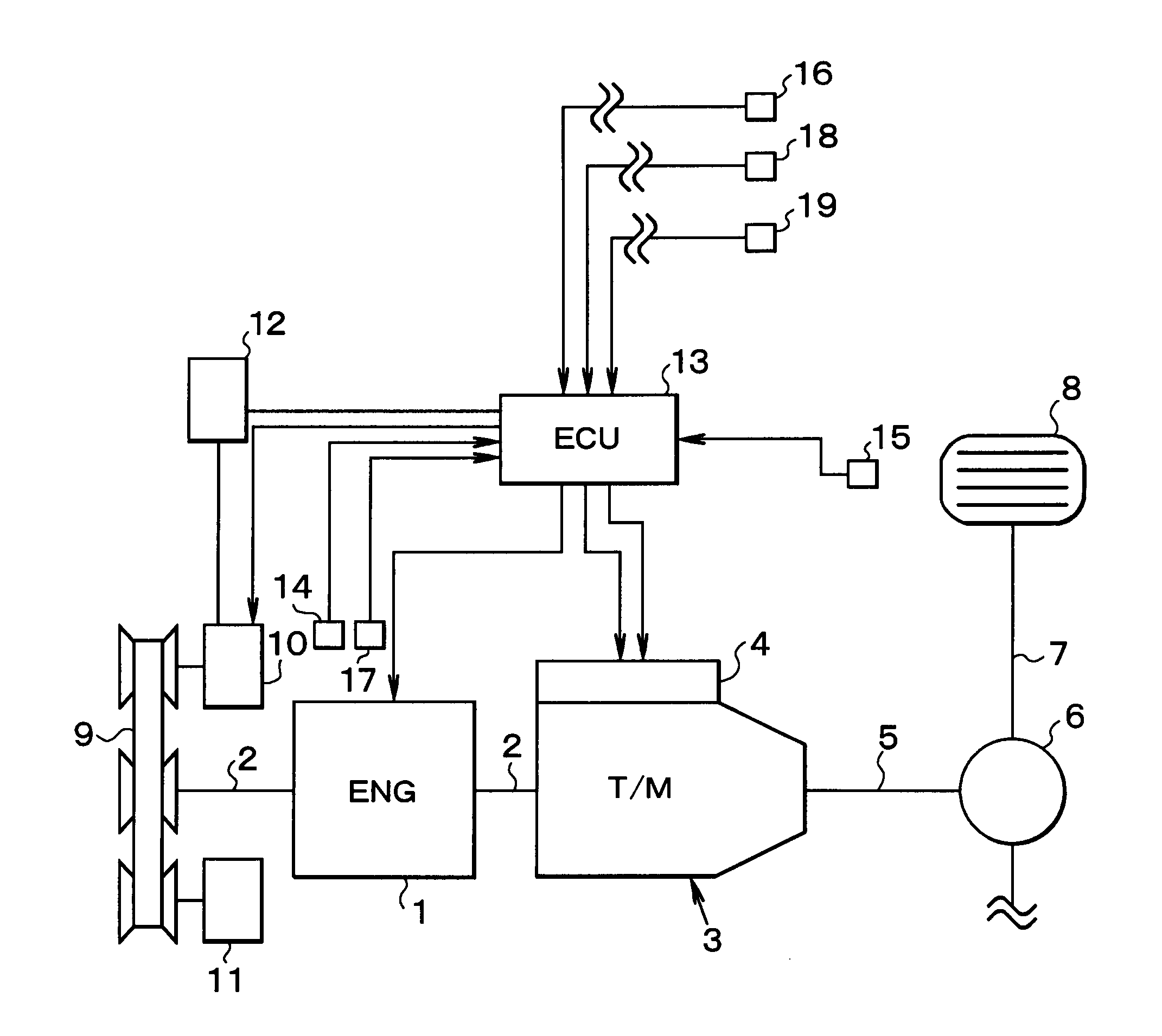
[0058]Next, the present invention will be explained in more detail. First of all, a vehicle to which the present invention is applied will be explained with reference to FIG. 18 schematically showing a structure of the vehicle. As shown in FIG. 18, the vehicle is provided with an internal combustion engine (as will be called a vehicle hereinafter) 1. Specifically, an engine possible to carry out a fuel-cut control by stopping a delivery of fuel thereto during inspiring air is used as the engine 1. A transmission 3 for changing a speed change ratio is connected with an output shaft (i.e., a crank shaft) 2 of the engine 1. Therefore, a torque of the engine 1 is outputted from the transmission 3 while being changed according to the speed change ratio. Specifically, the transmission 3 is provided integrally with a hydraulic control unit 4, and configured to change a speed change ratio thereof or to shift a gear stage thereof by controlling the hydraulic control unit 4 electrically. The ...


PUM


Abstract

A vehicle control system capable of reducing change in acceleration of the vehicle before and after the termination of fuel-cut control.Before the termination of the fuel-cut control, the vehicle control system reduces a pumping loss by increasing an air intake and a load torque of an auxiliary device thereby preventing the vehicle to be decelerated excessively, and after the termination of the fuel-cut control, the vehicle control system increases the load torque of the auxiliary device thereby preventing the vehicle to be accelerated abruptly. Therefore, the vehicle speed will not be lowered unnecessarily before the termination of the fuel-cut control so that an execution time of the fuel-cut control can be extended. Moreover, driving comfort can be improved by thus reducing a change in acceleration.

Description

TECHNICAL FIELD[0001]The present invention relates to a control system for controlling a driving force of a vehicle having an internal combustion engine, and especially to a system configured to carry out a fuel-cut control for selectively stopping the delivery of fuel to the internal combustion engine when the vehicle is being decelerated, and to control a driving force or a braking force resulting from carrying out the fuel-cut control.BACKGROUND ART[0002]An internal combustion engine such as a gasoline engine and a diesel engine are used as a prime mover of a vehicle. The internal combustion engine starts running autonomously when ignited while being rotated at a predetermined speed and delivering the fuel thereto. That is, it is unnecessary to deliver the fuel to the engine in case the engine is being rotated at a speed higher than a reactivatable lower limit speed at which the engine is allowed to rotate autonomously by delivering the fuel thereto, unless driving force is deman...

Claims


Application Information

Patent Timeline
Patent Type & Authority Applications(United States)
IPC IPC(8): B60W30/18B60W10/04B60W10/10F16H61/50
CPCB60W10/06Y10T477/63385B60W10/30B60W30/18072F02D29/02F02D41/123F02D41/126F02D41/1497F02D2250/18F02D2250/21Y02T10/42Y10T477/6333Y10T477/6403Y10T477/635B60W10/107Y02T10/40
Inventor MORIMURA, JUNICHIKODAMA, SHINYANIWA, SATORU
Owner TOYOTA JIDOSHA KK
Learn More