
Selective bond reduction in microfluidic devices

a technology of microfluidic devices and selective bonding, which is applied in the direction of component separation, lamination, printing, etc., can solve the problems of high associated production cost, limited feature complexity, and further labour-intensive processes with relatively low throughput , to achieve the effect of selectively reducing the bonding of materials

Inactive Publication Date: 2012-07-19
ATKIN MICAH
View PDF0 Cites 19 Cited by
  • Summary
  • Abstract
  • Description
  • Claims
  • Application Information

AI Technical Summary

Benefits of technology

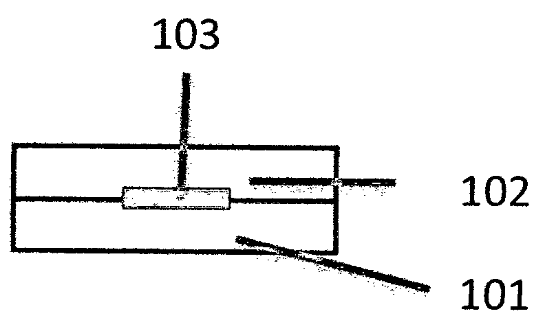
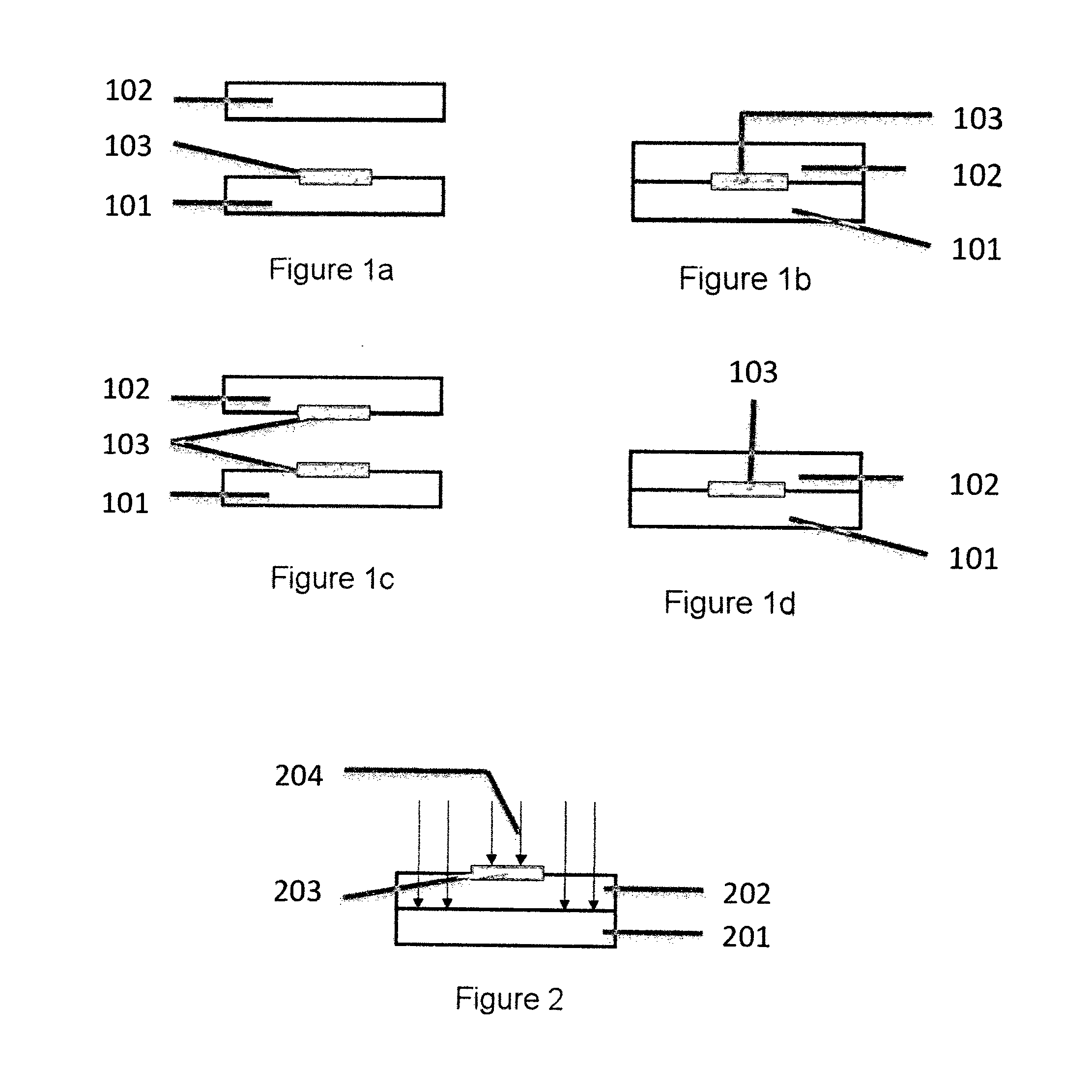
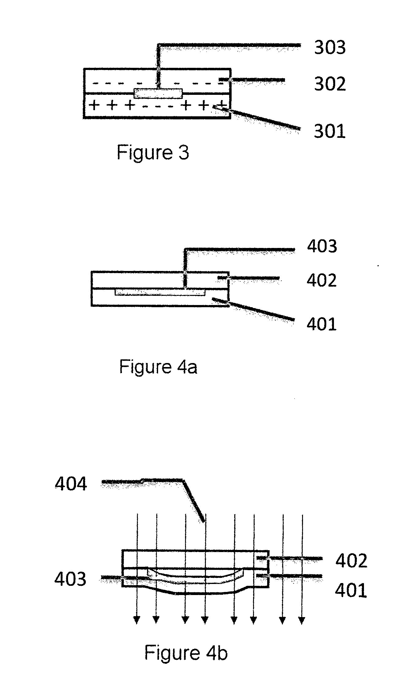
[0037]A bond-reducing material is used to either fully or partially prevent a bond forming in a spatially defined location, and may be used improve the surface characteristics in a microstructure.
[0040]In one embodiment, the bond-reducing material is selected from the group consisting of an ink: A) Colorants (including pigments, toners, and dyes) that provide colour contrast. B) Vehicles, or varnishes, that bind to the printed surface and may act as carriers for any colorants during the printing operation. C) Additives that influence the printability, film characteristics, drying speed, or end-use properties, such as the inclusion of chemical moieties for bond reduction. D) Solvents, which may help in formation of the vehicles, in reducing ink viscosity, adjusting drying properties, or resin compatibility.

Problems solved by technology

In polymer microfluidic fabrication many of the manufacturing approaches are limited to creating 2-dimensional or 2½-dimensional structures.
The most common of these approaches use either computer numerical control (CNC) micromilling, injection-moulding or hot embossing, which can generate only very limited feature complexity.
However, these are often serial fabrication processes that have alignment challenges when assembling micro-parts which lead to further labour-intensive processes with relatively low throughput and high associated production costs.
In polymer microfluidics, bonding represents a particularly difficult problem due to the requirements of maintaining the integrity of the microstructures while forming a good seal.
Typically selective bonding is the more expensive technique to implement in production but the spatial control of the bonding seal may be greater, reducing the risk of interfering with microstructures.
These are often causes of failure in these devices where the adhesive is exposed to the microfluidic channel.
However it can be difficult to selectively deposit adhesives in a volume manufacturing setting due the select availability of suitable adhesives and deposition techniques.
Some of the many issues include the adhesive viscosity requirement, the adhesive's lifetime prior to bonding, speed of deposition and deposition control.
From a manufacturing view the process requires relatively long processing times which limits the throughput capability.
Many of the reaction pathways created by these exposure techniques involve unstable free radical species.
However the suitability of these techniques has only been demonstrated for a few materials.
However this can be difficult to implement in a high speed production environment and still maintain the tight tolerances required for microstructured devices.
Generally the main problem with this technique is the difficulty of handling the solvents in the production environment.
Furthermore, for fluidic devices the solvent residues can provide a source of contamination, and the solvent may deform the microstructures.
For integration into the production environment, the main limitations are processing times, and limitation of compatible materials and number of layers that can be processed.
Due to the uniform heat conduction within the polymers which limits spatial resolution, the technique is only suitable for thin films and relatively large structures.
However for microstructures, this can introduce problems due the non specific heating causing deformation.
Due to these geometric constraints for bonding, ultrasonic sealing is limited in terms of its application to microfluidics.
For sealing microstructures the effectiveness is typically dependant limited by the deposition technique and evenly controlling the energy absorbed.
For many microstructures in polymeric devices this is further complicated by the deformation of the structure during the bonding process.
The use of adhesive tapes for microfluidics is further complicated by chemical or biochemical incompatibility with many assays, and the dimensional limitations provided by the machining processes of these tapes.
However, with all these area bonding techniques a problem arises where a bond is not required, or required at a different strength, in a selective area between two surfaces in contact with one another.
In many cases selective bonding is not an option due to material compatibility, cost, speed and dimensional constraints.
As with other afore mentioned lateral and vertical flow devices the effect of capillary action or gravity driven flow is limited to relatively simple protocols as multiple flows from different sources and complex flow profiles, such as backwashing, are not feasible.
Limitations of such systems include the reliance on capillary or gravity flow for fluid movement, which inherently causes reproducibility issues with regards to flow rate and limitations in terms of suitability of assay protocols.
These capillary and gravity flow devices are limited in terms of performing only simple one-step assays; they provide imprecise handling of fluid volumes which affects the overall reproducibility; they are restricted in terms of the maximum volume they can use and therefore limits the sensitivity; they are susceptible to matrix effects obstructing pores; and they typically provide a qualitative or semi-quantitative response [Analytical and Bioanalytical Chemistry, Volume 393, Number 2, January 2009, pp.
Most of these difficulties in optical measurement within microstructures arise from the tight dimensional constraints, reduced path lengths, and reduced fluid volumes leading to much smaller signal responses.
However a problematic aspect of microfluidic device manufacture is the increase in cost associated with the manufacturing processes required to achieve smaller dimensions and their associated tolerances.
However for polymer device fabrication it is generally known that as the dimensions of a feature on a device decreases in size and the tolerance required, the cost and difficulty in implementing in a mass manufacturing environment increases greatly.
This is particularly problematic in microfluidics where the tolerance requirements are often much less than 100 micron.

Method used


Image

  • Selective bond reduction in microfluidic devices
  • Selective bond reduction in microfluidic devices
  • Selective bond reduction in microfluidic devices

Examples


Embodiment Construction

[0088]It is convenient to describe the invention herein in relation to particularly preferred embodiments relating to microfluidic devices. However, the invention is applicable to a wide range of situations and products and it is to be appreciated that other constructions and arrangements are also considered as falling within the scope of the invention. Various modifications, alterations, variations and or additions to the construction and arrangements described herein are also considered as falling within the ambit and scope of the present invention.

[0089]The invention overcomes the limitations described for the bonding of structured layers by providing a method for selectively reducing the bonding of materials. In the context of this invention a bond-reducing material is defined as a material that is used to reduce the strength of a bond between two surfaces, or prevent a bond that would have otherwise occurred between two surfaces. The bond reducing material may be applied prior ...


PUM

PropertyMeasurementUnit
Lengthaaaaaaaaaa
Lengthaaaaaaaaaa
Lengthaaaaaaaaaa

Abstract

The invention overcomes the limitations described for the bonding of structured layers by providing a method for selectively reducing the bonding of materials. In its most generic form, the invention uses a bonding technique in combination with a printing method for modifying or covering at least one portion of a surface to either fully or partially prevent localised bonding. The structuring process may act upon the layers either before or after the bonding of the layers. The invention overcomes the limitations described in the application of affinity chromatography by providing a planar substrate with discrete optical detection flow cells that contain porous material and have connecting microchannels for fluid delivery and / or removal, and a method for making the same.

Description

CROSS REFERENCE TO RELATED APPLICATIONS[0001]This application claims priority to U.S. provisional patent application No. 61 / 247,026, filed on 30 Sep. 2009, the entire contents of which are incorporated herein by reference.FIELD OF THE INVENTION[0002]This invention relates generally to the manufacture of complex layered materials and devices. More particularly, the present invention relates to methods of selectively bonding two surfaces by selectively modifying or coating at least one surface prior to bonding to reduce, or prevent, the bonding in the selected areas. The field of this invention also extends to the manufacture of complex polymeric materials and devices, in particular those for use in microfluidic applications.[0003]This invention also relates to structures, devices and methods of manufacture for optical imaging in microfluidic devices using porous material inside detection flow cells.BACKGROUND OF THE INVENTION[0004]Many industries have moved to using layered materials...

Claims


Application Information

Patent Timeline
IPC IPC(8): G01N30/02B32B7/14B32B37/02B32B38/14B32B38/10
CPCB01L3/5023B01L3/502707B01L3/502738B01L2200/0689B01L2300/0636B01L2300/0681B01L2300/069B01L2300/0816B01L2300/0861B01L2300/0864B01L2300/0867B01L2300/0887B01L2400/0605B01L2400/0638B01L2400/0683B29C65/006B29C65/008B29C65/02B29C65/08B29C65/1406B29C65/1409B29C65/1412B29C65/1425B29C65/16B29C65/4895B29C66/004B29C66/54B29C66/71B29L2031/756B32B37/0076B32B38/145F04B19/006F16K99/0001F16K2099/008F16K2099/0094B29C65/1635B29C65/1696B29C65/484B29C65/48B29C65/4815B29C65/483Y10T428/24802B29K2023/0633B29K2023/065B29K2033/12B29K2069/00B29K2067/003B29K2067/006B29K2025/04B29K2079/08B29K2079/085B29K2055/02B29K2075/00B29K2001/12B29K2077/00B29K2071/00B29K2027/06B29K2027/08B29K2027/16B29K2023/38B29K2081/06B29K2027/18B29K2059/00B29K2001/18B29K2033/26B29K2023/00B29K2023/12B29K2023/06B29C66/7212B29K2309/08B29K2023/04B29K2023/10B29K2083/00B29K2033/08B29K2025/06B29K2023/18
Inventor ATKIN, MICAH
Owner ATKIN MICAH
Learn More