
Offset valve bore for a reciprocating pump

a technology of offset valve and reciprocating pump, which is applied in the direction of machines/engines, liquid fuel engines, positive displacement liquid engines, etc., can solve the problems of shortening the and achieve the effect of increasing the useful operating life of the fluid end and reducing the stress of the fluid in us

Inactive Publication Date: 2012-07-19
S P M FLOW CONTROL
View PDF2 Cites 22 Cited by
  • Summary
  • Abstract
  • Description
  • Claims
  • Application Information

AI Technical Summary

Benefits of technology

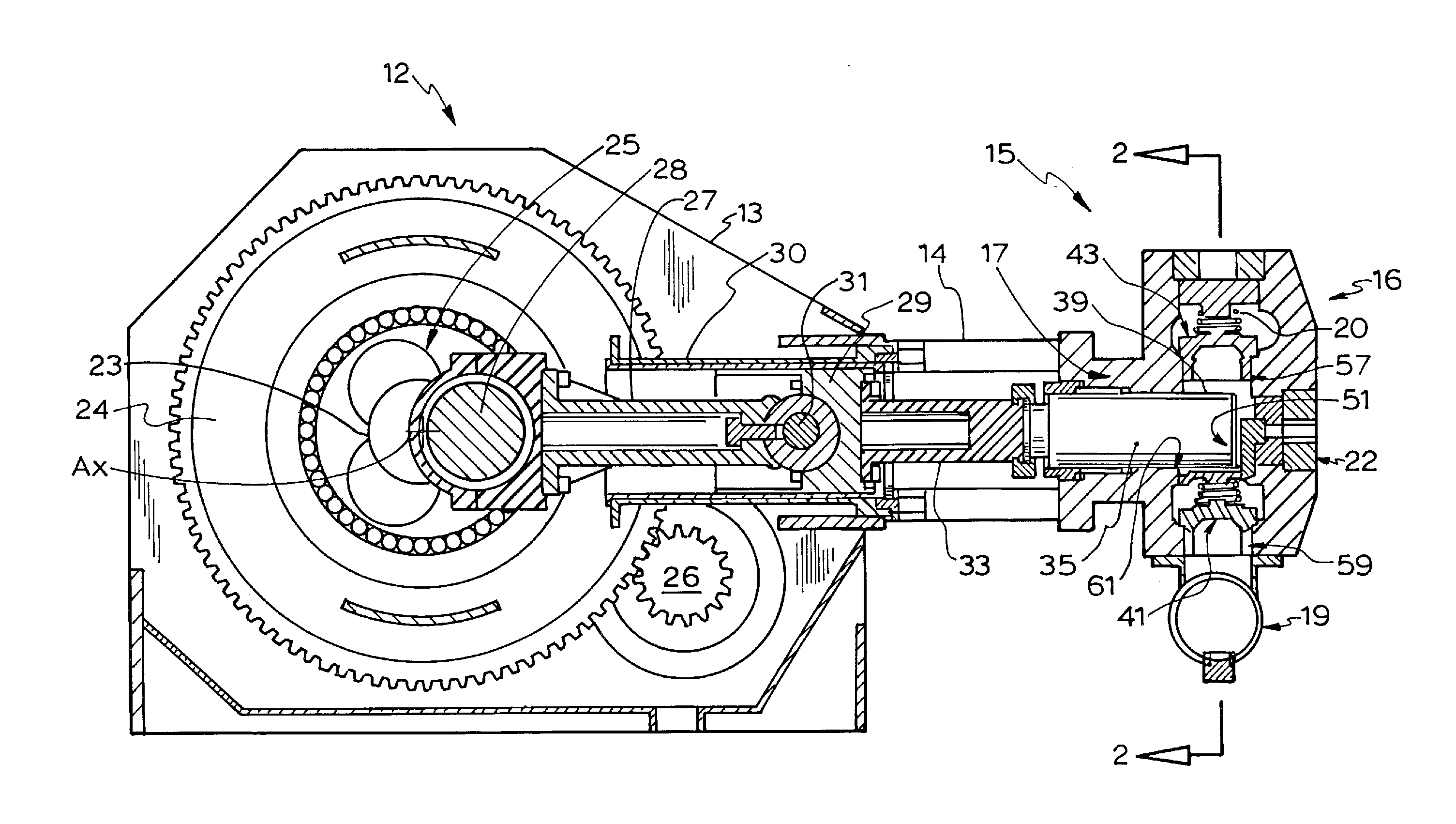
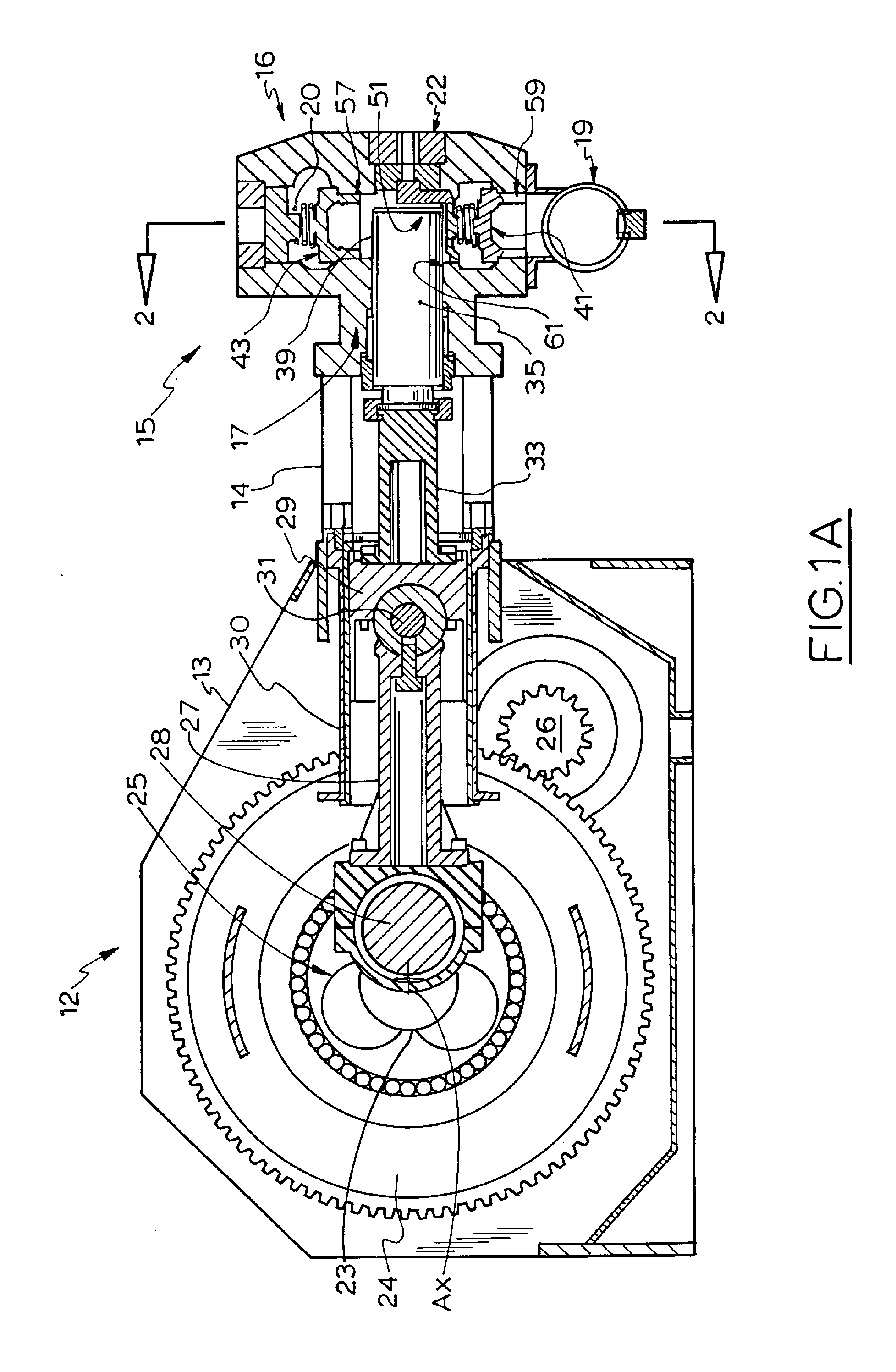
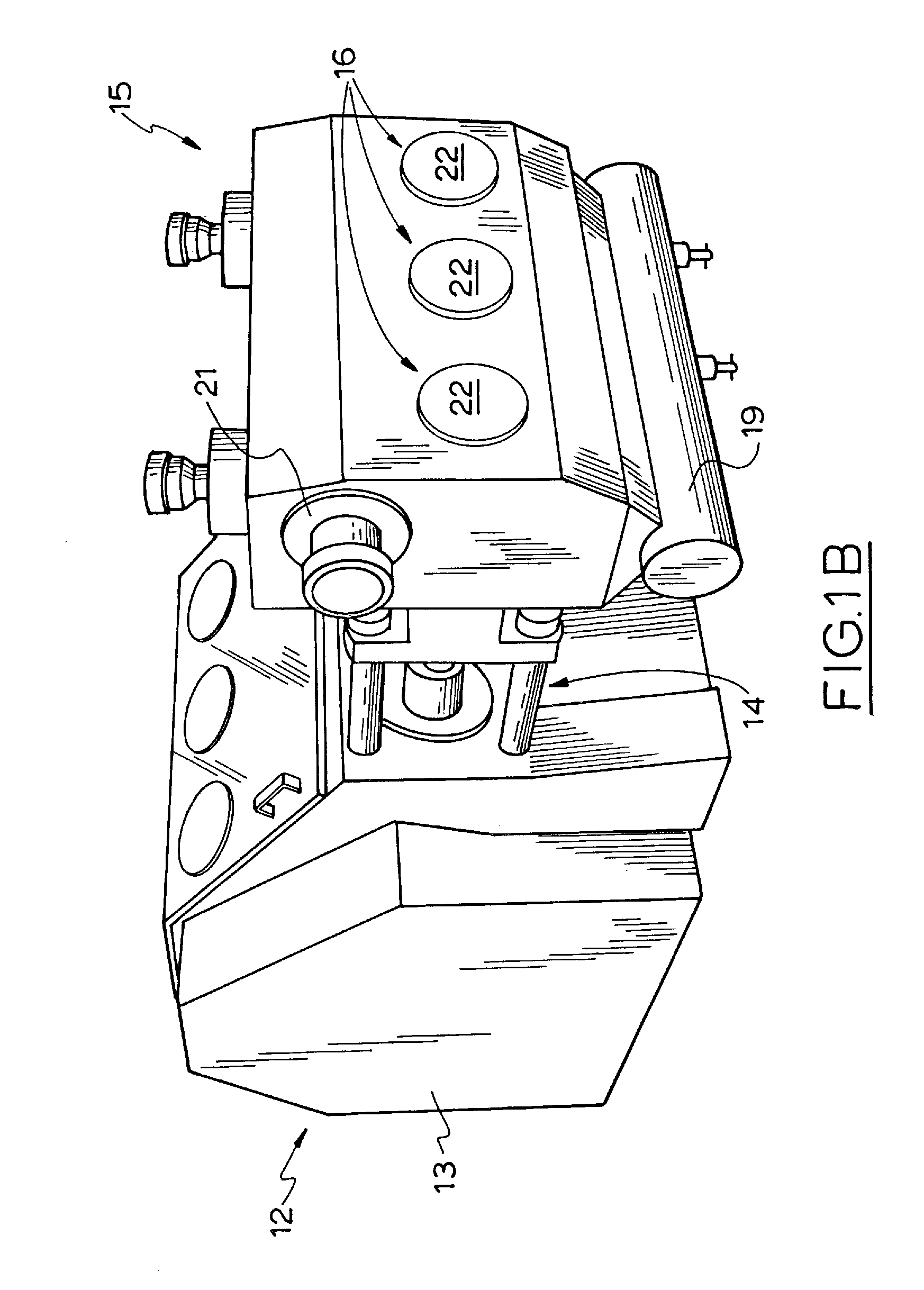
"The patent describes a fluid end for a multiple reciprocating pump assembly that has three or five plunger bores. Each plunger bore has a plunger bore axis and is designed to receive a reciprocating plunger. The plunger bores are arranged across the fluid end to define a central plunger bore and lateral plunger bores located on either side of the central plunger bore. The fluid end also includes at least three respective suction valve bores and at least three respective discharge valve bores. The plunger bores and valve bores are offset from their respective axes in a way that reduces stress on the fluid in use. This design increases the useful operating life of the fluid end. The patent also describes different configurations of the fluid end that may be used in fracking pumps in oilfield operations."

Problems solved by technology

These reciprocating pumps run for relatively short periods of time, but they operate on a frequent basis and oftentimes at extremely high pressures.
The occurrence of high stress at these areas can shorten the life of the fluid end.

Method used


Image

  • Offset valve bore for a reciprocating pump
  • Offset valve bore for a reciprocating pump
  • Offset valve bore for a reciprocating pump

Examples


example 1

Inward Offsetting

[0115]In the first set of tests a single (or mono) block fluid end and a triplex fluid end were each modeled. The single block fluid end was modeled with one of the valve bores offset and an end was modified with an end support. With the triplex fluid end one of the lateral (outside) valve bores was inwardly offset, as compared with a triplex pump in which both lateral valve bores may be inwardly offset. The fluid end configurations modeled included one (e.g. lateral) discharge 57 and suction 59 bore being inwardly offset by 1.5 inches and by 2 inches.

[0116]The stress result modeled by FEA was correlated to the Von Mises yield criterion (in psi) and the results were plotted for each of zero offset (that is, an existing fluid end), and 1.5 inches and 2 inches offset (that is, a new fluid end) and offset with an end support. The results are shown in the graphs of FIG. 18 (which shows data point results for both 1.5 inches and 2 inches offset) and FIG. 19 (which repres...

example 2

Outward Offsetting

[0118]In the second set of tests, the outward offsetting of one of the lateral (outside) valve bores was modeled. The fluid end configurations tested included one lateral suction 57 and suction 59 bore being outwardly offset by 1.5 inches and by 2 inches. The results for a 2 inch offset are shown in FIG. 20. For a 2 inch outward offset in a triplex, with no adjustment for a resultant thinning in adjacent wall material, the FEA modeling resulted in an increase in stress at the intersection of plunger and valve bores (2nd rightmost bar). However, in the FEA model, as soon as the wall was modified with an end support that was 2 inches in length (or thickness) extending along the entire surface of the outer wall (see e.g. FIGS. 1C and 1D), the overall stress reduction in the fluid end was around 29% (from ˜97,000 psi to less than 69,000 psi). Again, it was noted that such a stress reduction would be likely to significantly extend the useful operating life of the fluid ...


PUM


Abstract

A fluid end 15 for a multiple reciprocating pump assembly 12 comprises at least three plunger bores 61 or 91, each for receiving a reciprocating plunger 35. Each plunger bore has a plunger bore axis 65 or 95. The plunger bores are arranged across the fluid end to define a central plunger bore with lateral plunger bores located on either side. The fluid end 15 also comprises at least three respective suction valve bores 59 or 89 in fluid communication with the plunger bores. Each suction valve bore can receive a suction valve 41 and has a suction valve bore axis 63 or 93. The fluid end 15 also comprises at least three respective discharge valve bores 57 or 87 that can receive a discharge valve 43 and are in fluid communication with the plunger bores. Axes of suction and discharge valve bores are offset in the fluid.

Description

CROSS-REFERENCE TO RELATED APPLICATIONS[0001]This application claims priority to provisional application 61 / 421,453 filed Dec. 9, 2010.TECHNICAL FIELD[0002]An arrangement is disclosed whereby a valve bore is offset from a plunger bore in a fluid end of a reciprocating pump to relieve stress.BACKGROUND OF THE DISCLOSURE[0003]In oil field operations, reciprocating pumps are used for various purposes. Reciprocating pumps are used for operations such as cementing, acidizing, or fracturing of a subterranean well. These reciprocating pumps run for relatively short periods of time, but they operate on a frequent basis and oftentimes at extremely high pressures. A reciprocating pump is mounted to a truck or a skid for transport to various well sites and must be of appropriate size and weight for road and highway regulations.[0004]Reciprocating pumps or positive displacement pumps for oil field operations deliver a fluid or slurry, which may carry solid particles (for example, a sand proppan...

Claims


Application Information

Patent Timeline
Patent Type & Authority Applications(United States)
IPC IPC(8): F04B47/00
CPCF04B1/0456F04B53/1095F04B27/10F04B1/0536F04B23/06F04B47/00F04B39/122F04B1/00F04B27/00F04B53/16
Inventor BAYYOUK, JACOB A.MANSON, DAVID M.MACKENZIE, DONALDDAVIES
Owner S P M FLOW CONTROL
Learn More