Method for manufacturing LED with transparent ceramics
- Summary
- Abstract
- Description
- Claims
- Application Information
AI Technical Summary
Benefits of technology
Problems solved by technology
Method used
Image


Examples
embodiment 1
[0037]The preparation of a white light LED with MA (magnesium aluminate spinel) transparent ceramic is taken as the embodiment.
[0038]1) Preparation of powder: adding 2 wt % of Ce: YAG (the Ce content is 1 at %) yellow fluorescent powder to the MA transparent ceramic powder, fully mixing through the wet process by ball milling, drying the mixture and then obtaining the fluorescent transparent ceramic powder; during the preparation process of the powder, if the mixture is prepared through the dry process, the drying treatment is not required, and the fluorescent transparent ceramic powder can be obtained after fully mixing.
[0039]2) Forming process: performing vacuum hot-pressing forming on the fluorescent transparent ceramic powder added with a sintering additive so as to obtain a sintered body of the fluorescent transparent ceramic; and performing annealing treatment on the sintered body within a certain temperature range, then performing hot isostatic pressing and then performing co...
embodiment 2
[0046]The preparation of a white light LED with MA transparent ceramic is taken as the embodiment.
1) Preparation of powder: adding 7 wt % of commercially available yellow fluorescent powder to the MA transparent ceramic powder and fully mixing so as to obtain the fluorescent transparent ceramic powder.
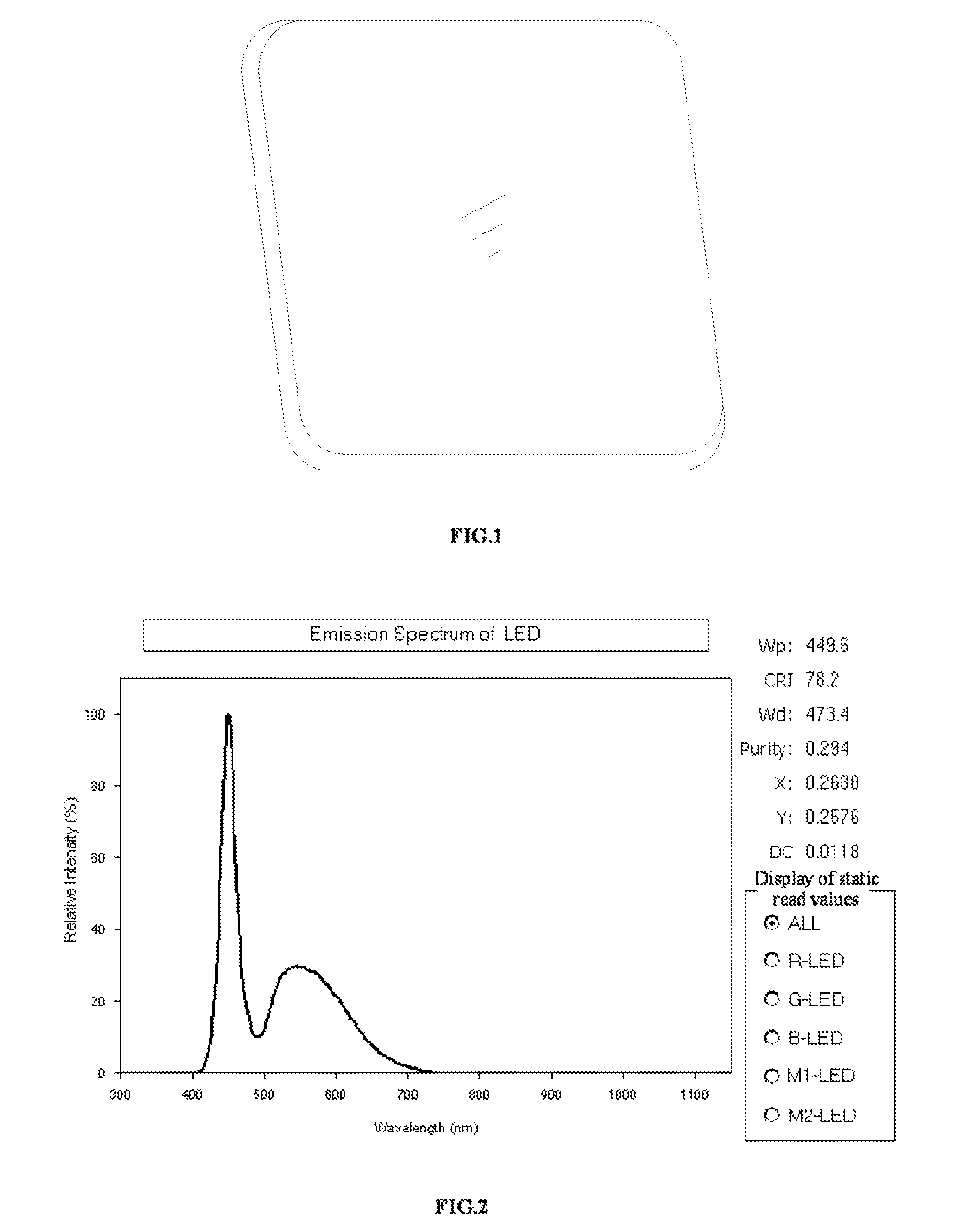
2) Forming process: performing vacuum hot-pressing forming on the fluorescent transparent ceramic powder added with a sintering additive so as to obtain a sintered body of the fluorescent transparent ceramic; and performing annealing treatment on the sintered body within a certain temperature range, and then performing hot isostatic pressing, cutting and polishing treatment so as to obtain the MA fluorescent transparent ceramic, shown as FIG. 1.
3) LED packaging: assembling the prepared MA fluorescent transparent ceramic and a blue light LED chip to form an LED device. The output of white light is realized. The spectrogram of the obtained LED device is shown as FIG. 2.
[0047]The results ...
embodiment 3
[0048]The preparation of a three-wavelength white light LED with MA transparent ceramic is taken as the embodiment.
1) Preparation of powder: adding commercially available green, yellow and red fluorescent powders to the MA transparent ceramic powder according to 0.4 wt %, 2 wt % and 0.2 wt % respectively and fully mixing so as to obtain the fluorescent transparent ceramic powder.
2) Forming process: performing vacuum hot-pressing forming on the fluorescent transparent ceramic powder added with a sintering additive so as to obtain a sintered body of the fluorescent transparent ceramic; and performing annealing treatment on the sintered body within a certain temperature range, and then performing hot isostatic pressing, cutting and polishing treatment so as to obtain the MA fluorescent transparent ceramic.
3) LED packaging: assembling the prepared MA fluorescent transparent ceramic and a blue light LED chip to form an LED device.
PUM
| Property | Measurement | Unit |
|---|---|---|
| Color | aaaaa | aaaaa |
| Transparency | aaaaa | aaaaa |
Abstract
Description
Claims
Application Information
 - R&D
- Intellectual Property
- Life Sciences
- Materials
- Tech Scout
- Unparalleled Data Quality
- Higher Quality Content
- 60% Fewer Hallucinations
Browse by: Latest US Patents, China's latest patents, Technical Efficacy Thesaurus, Application Domain, Technology Topic, Popular Technical Reports.
© 2025 PatSnap. All rights reserved.Legal|Privacy policy|Modern Slavery Act Transparency Statement|Sitemap|About US| Contact US: help@patsnap.com