
Compensated compressed gas storage systems

Active Publication Date: 2012-07-12
HYDROSTOR
View PDF6 Cites 47 Cited by
  • Summary
  • Abstract
  • Description
  • Claims
  • Application Information

AI Technical Summary

Benefits of technology

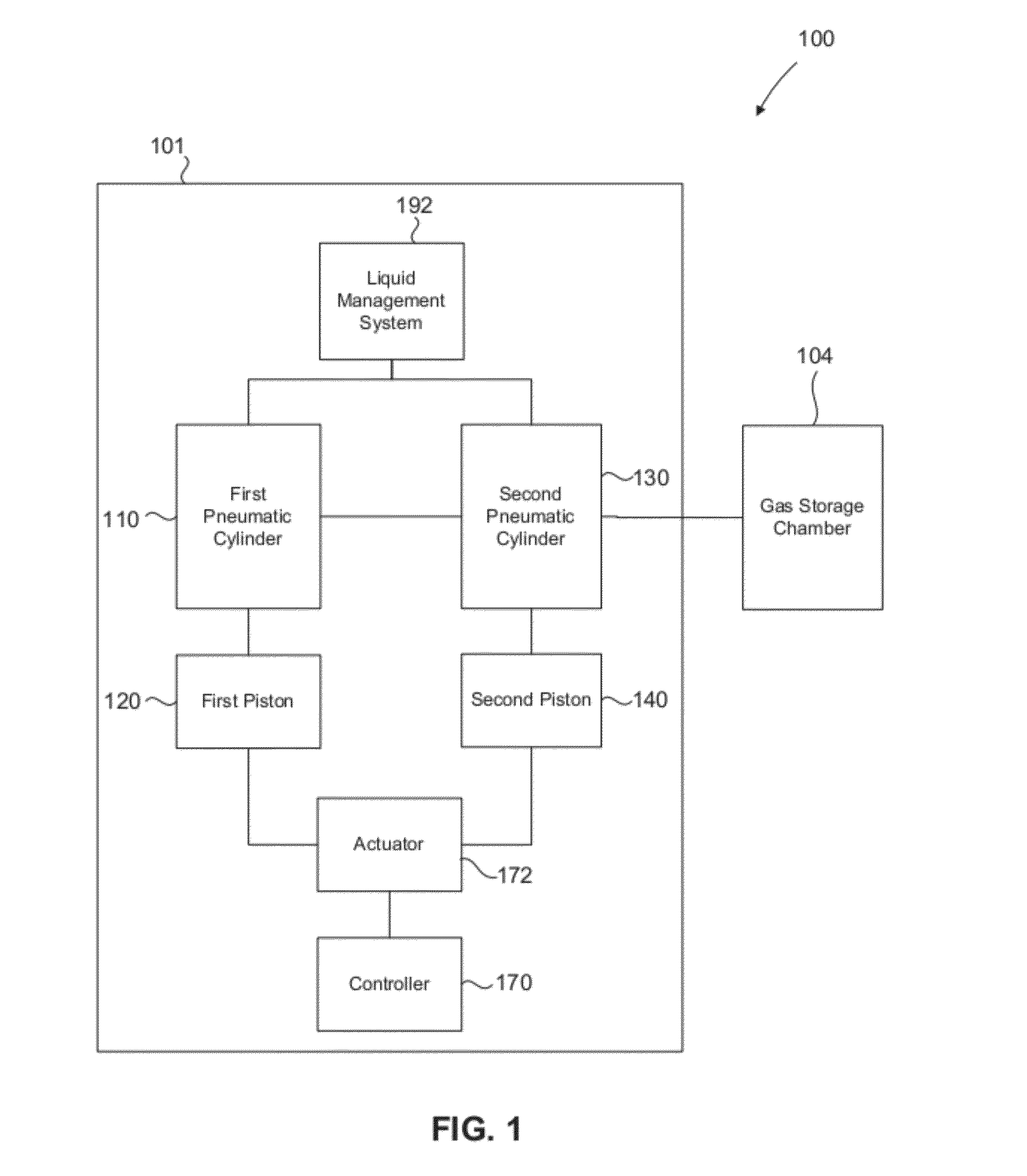
[0011]In some embodiments, such systems, devices and methods can be configured to optimize the efficiency of such compression, expansion, and / or storage of natural gas, including efficiently controlling the temperature and / or water content of natural gas during such compression, expansion, and / or storage. In some embodiments, an apparatus suitable for use in a compressed gas-based energy storage and recovery system includes a pneumatic cylinder and a liquid management system. The pneumatic cylinder includes a pneumatic chamber having a first fluid port and a second fluid port. The pneumatic chamber is fluidically coupleable to and configured to receive a first mass of compressed gas from a compressed gas storage chamber via the first fluid port. The pneumatic chamber is configured to permit the first mass of compressed gas to expand therein. The liquid management system is fluidically coupleable to the pneumatic chamber via the second fluid port and is configured to transfer a first volume of liquid from the liquid management system into the pneumatic chamber. The first volume of fluid is configured to dehydrate the first mass of compressed gas in the pneumatic chamber.

Problems solved by technology

In such a system, however, the air may still achieve substantial temperatures during each stage of compression, prior to being cooled, which will introduce inefficiencies in the system.
During periods of lower demand, natural gas in excess of demand may be burned at a flare, thus wasting this natural resource.
Thus, a minimum quantity of gas (at a given temperature) would need to be maintained in the cavern—removal of too much gas could lead to collapse of the cavern and / or lead to a violation of operation regulations.
This requirement of retaining a certain pressure / quantity of stored gas in the cavern limits the effective working capacity of the storage structure.
Other caverns may have a maximum allowable operating pressure less than 0.75 psi per foot of depth and / or a minimum allowable operation pressure greater than 0.2 psi per foot of depth and thus, further limiting the effective working capacity of the storage structure.
The requirement to maintain a minimum gas pressure, and thus a minimum quantity of gas, in the storage cavern means that a significant quantity of stored gas may not be recovered from the storage cavern, and thus not available for use or sale.

Method used


Image

  • Compensated compressed gas storage systems
  • Compensated compressed gas storage systems
  • Compensated compressed gas storage systems

Examples


Embodiment Construction

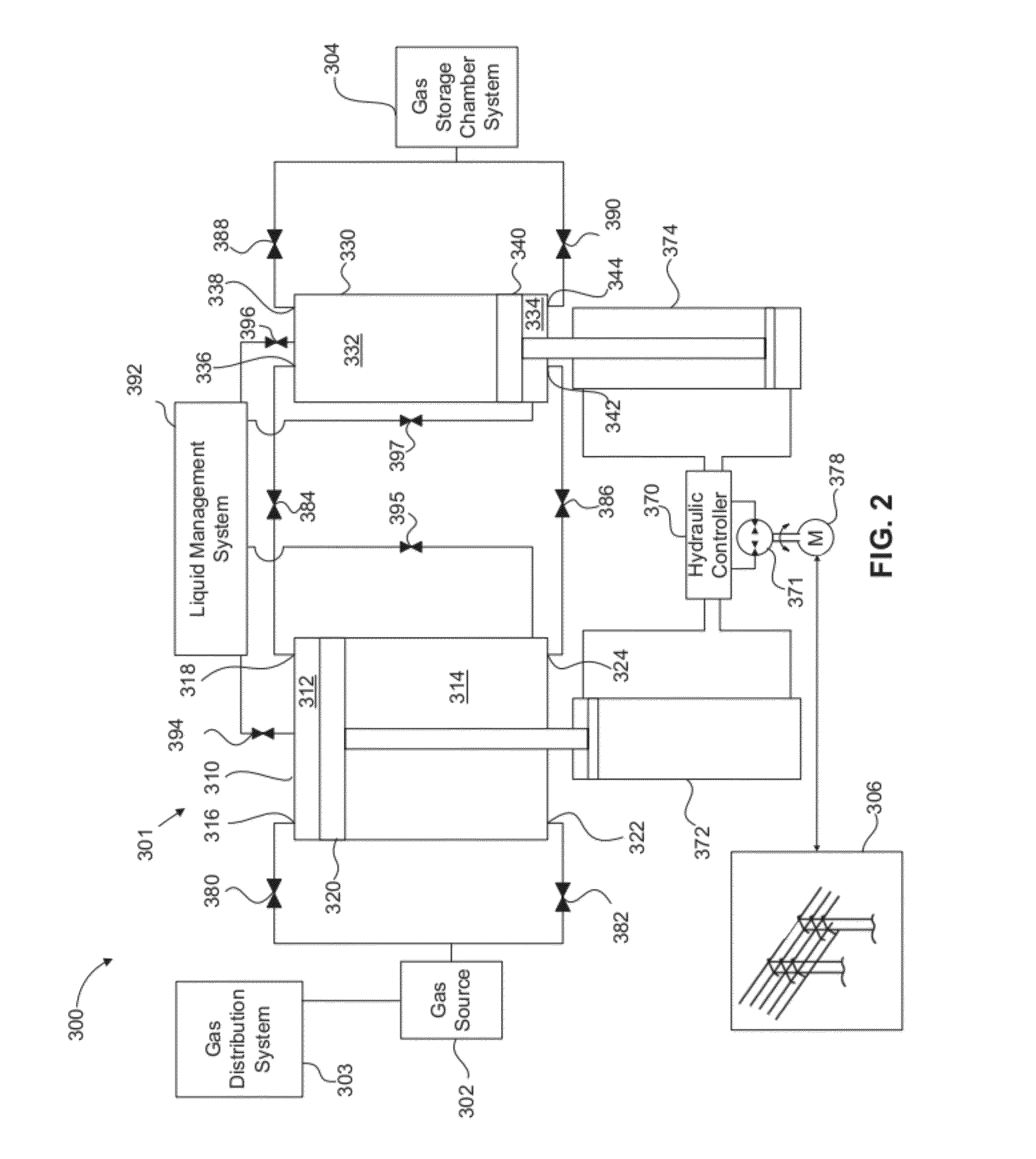
[0030]Systems, devices and methods for optimizing and efficiently operating a gas compression and / or expansion system are disclosed herein. Such systems, devices and methods can be configured for heat transfer during compression and / or expansion, as well as for dehydration of the gas during compression and / or expansion. Also disclosed herein are systems, methods and devices for storing energy in the form of compressed gas, such as natural gas, in underground storage caverns.

[0031]The compressed gas energy storage systems can use one or more compressor / expander devices to move (or be moved by) gas within the system, and systems and methods are described herein to operate the compressed gas energy storage system in its most efficient regime, in a compression mode and / or in an expansion mode. As described herein, in some embodiments, systems and devices can be to used to compress and / or expand a gas, such as natural gas, and / or to pressurize and / or pump a liquid, such as water or glyco...


PUM


Abstract

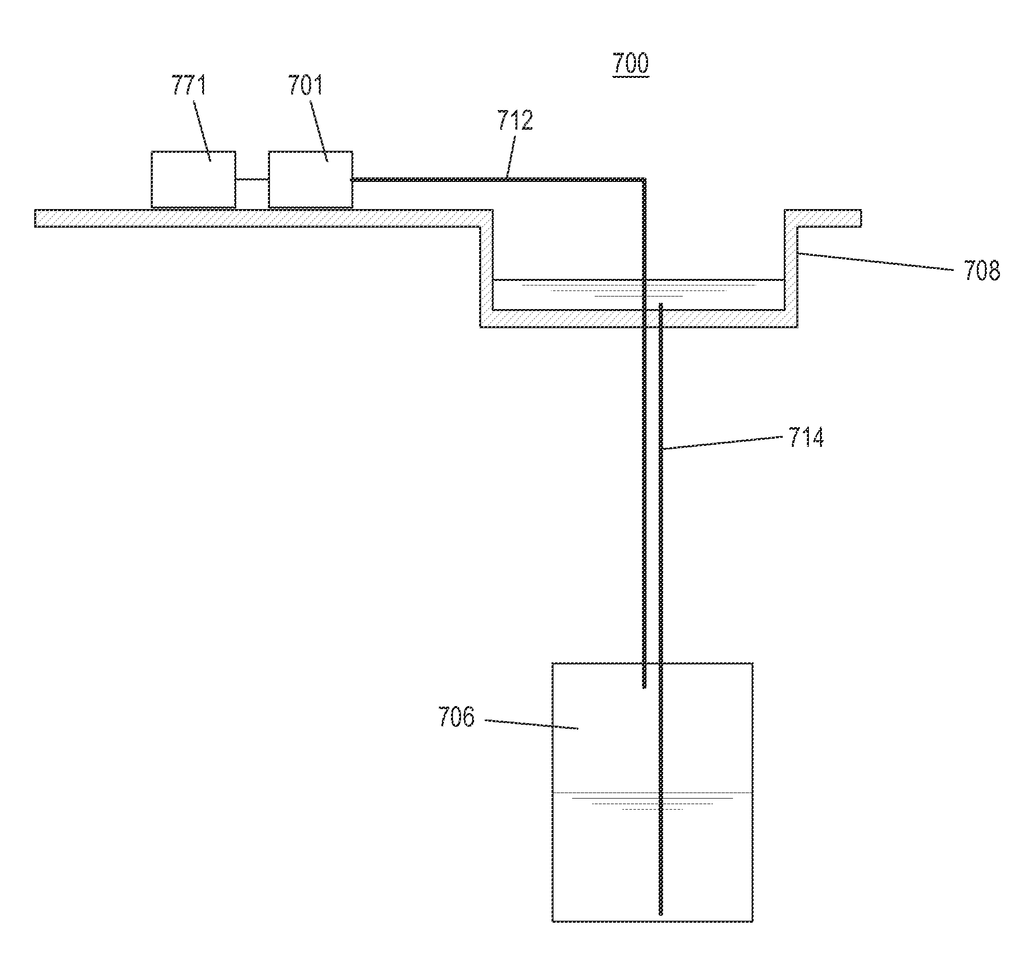
Systems, devices and methods for the compression, expansion, and / or storage of a gas are described herein. An apparatus suitable for use in a compressed gas-based energy storage and recovery system includes a pneumatic cylinder having a working piston disposed therein for reciprocating movement in the pneumatic cylinder, a hydraulic actuator coupled to the working piston, and a hydraulic controller fluidically coupleable to the hydraulic actuator. The apparatus is fluidically coupleable to a compressed gas storage chamber which includes a first storage chamber fluidically coupleable to the pneumatic chamber, and a second storage chamber is fluidically coupleable to the first storage chamber. The first storage chamber is disposed at a first elevation and is configured to contain a liquid and a gas. The second storage chamber is disposed at a second elevation greater than the first elevation, and is configured to contain a volume of liquid.

Description

CROSS-REFERENCE TO RELATED APPLICATIONS[0001]This application claims priority to and the benefit of U.S. Provisional Patent Application Ser. No. 61 / 432,904, entitled “Compensated Compressed Gas Storage Systems,” filed on Jan. 14, 2011, the disclosure of which is hereby incorporated by reference herein in its entirety.[0002]This application is also related to U.S. patent application Ser. No. 13 / 294,675, entitled “Systems and Methods for Compressing and / or Expanding a Gas Utilizing a Bi-Directional Piston and Hydraulic Actuator,” filed on Nov. 11, 2011, and U.S. patent application Ser. No. 13 / 294,862, entitled “Systems and Methods for Optimizing Thermal Efficiency of a Compressed Air Energy Storage System,” filed on Nov. 11, 2011, the disclosures of which are incorporated herein by reference in their entirety.BACKGROUND[0003]The invention relates generally to systems, devices and methods for the compression, expansion, and / or storage of a gas, such as air or natural gas, and particula...

Claims


Application Information

Patent Timeline
IPC IPC(8): F15B1/027
CPCF02C6/16Y02E60/15H02J15/006Y02E60/16
Inventor INGERSOLL, ERIC D.ABORN, JUSTIN A.BLIESKE, MATTHEWMARCUS, DAVIDBROOKSHIRE, KYLE
Owner HYDROSTOR
Learn More