Systems and methods for search and rescue light control for a rotorcraft

Active Publication Date: 2021-01-05
HONEYWELL INT INC
View PDF14 Cites 1 Cited by
  • Summary
  • Abstract
  • Description
  • Claims
  • Application Information

AI Technical Summary

Benefits of technology

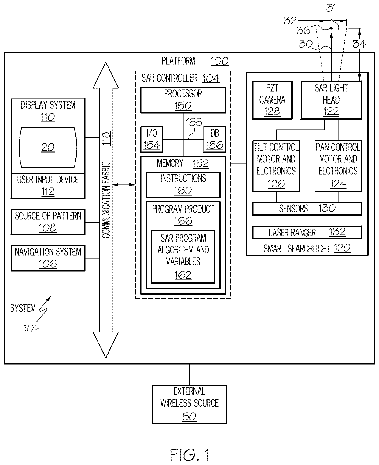
This patent describes a system and method for controlling a search and rescue (SAR) light on a rotorcraft. The system includes a pan control motor, a tilt control motor, a navigation system, a source of a cartesian pattern, and a controller operationally coupled to the navigation system and the source of cartesian pattern. The controller receives the cartesian pattern and determines an initial light head orientation based on the real-time rotorcraft state. The controller then generates a pan command and a tilt command for the SAR light, which are transmitted to the pan control motor and the tilt control motor, respectively. The pan control motor causes the beam axis to pan, while the tilt control motor causes the beam axis to tilt. The system also includes a pan-tilt-zoom (PTZ) camera that captures a video stream and continuously has a field of view centered on the beam axis. The PTZ camera can zoom in or out based on the delta-range. The technical effect of this system is to provide a more efficient and effective means to control the SAR light on a rotorcraft, allowing for quicker and more accurate response to emergency situations.

Problems solved by technology

These missions are dynamic and can be very technically difficult.
Maintaining the rotorcraft attitude while controlling the searchlight beam of light is cognitively demanding.
Moreover, maneuvering the direction / location of the searchlight beam of light on the ground is difficult under normal circumstances, even with searchlight configurations that provide pan and tilt control.

Method used


Image

  • Systems and methods for search and rescue light control for a rotorcraft
  • Systems and methods for search and rescue light control for a rotorcraft
  • Systems and methods for search and rescue light control for a rotorcraft

Examples


Embodiment Construction

[0018]The following detailed description is merely illustrative in nature and is not intended to limit the embodiments of the subject matter or the application and uses of such embodiments. As used herein, the word “exemplary” means “serving as an example, instance, or illustration.” Thus, any embodiment described herein as “exemplary” is not necessarily to be construed as preferred or advantageous over other embodiments. The embodiments described herein are exemplary embodiments provided to enable persons skilled in the art to make or use the invention and not to limit the scope of the invention that is defined by the claims. Furthermore, there is no intention to be bound by any expressed or implied theory presented in the preceding technical field, background, summary, or the following detailed description.

[0019]As used herein, control of a search and rescue (SAR) light (i.e., a device or apparatus that projects a searchlight beam of light) includes the desired control of the sear...


PUM


Abstract

Provided are systems and methods for controlling a search and rescue (SAR) light on a rotorcraft. The system includes a processor programmed to: for each cartesian input point in a sequence defining a cartesian pattern, determine an initial light head orientation as a function of the real-time rotorcraft state; generate and transmit a pan command and a tilt command as a function of the initial light head orientation and the cartesian input point; and identify a delta-range. A pan-tilt-zoom (PTZ) camera is configured to continuously slave and have a field of view centered on a beam axis of the SAR light. The PTZ camera captures a video stream and transmits it; zooms in on the field of view of the PTZ camera when the delta-range is positive; and zooms out on the field of view of the PTZ camera when the delta-range is negative.

Description

TECHNICAL FIELD[0001]The technical field generally relates to navigational aids, and more particularly relates to systems and methods for search and rescue light control for a rotorcraft.BACKGROUND[0002]Rotorcraft Searchlights are illumination apparatus mounted under the belly or chin of a rotorcraft. They generate a beam of light that may be used to illuminate a point of interest on the ground while the rotorcraft is in the air. When the direction / location of the searchlight beam of light is controlled, it may facilitate operations of search and rescue missions. Some conventional searchlight configurations are rigidly mounted, in which case, the rotorcraft itself must maneuver in order to re-orient and control the direction / location of the searchlight beam of light. Other conventional searchlight configurations provide pan and tilt control to maneuver the direction / location of the searchlight beam of light on the ground, independent of the rotorcraft movement.[0003]During a Search ...

Claims


Application Information

Patent Timeline
IPC IPC(8): B64D47/04B64D47/08B60Q1/24G03B15/00
CPCB64D47/04B64D47/08B60Q1/24G03B15/006B64D47/02B60Q1/245G03B37/02B64C27/04H04N23/60H04N23/62H04N23/695
Inventor DAS, SHOUVIKSETHURAMAN, DEEPTHISRINIVASULU, ANUPAMA
Owner HONEYWELL INT INC
Why Eureka
Try Eureka