
Laminous multi-polymeric high amperage over-molded connector assembly for plug-in hybrid electric vehicle charging

a hybrid electric vehicle and connector technology, applied in the field of electric connectors, can solve the problems of affecting the reliability of the product, and affecting the service life of the connector, so as to reduce the risk of tampering, and improve the product reliability

Active Publication Date: 2012-07-05
GENERAL CABLE TECH CORP
View PDF8 Cites 35 Cited by
  • Summary
  • Abstract
  • Description
  • Claims
  • Application Information

AI Technical Summary

Benefits of technology

The invention is a low-cost, attractive, ergonomic, and adaptable connector for electric vehicles. It has several features such as a spring latch that allows water to drain out of the connector, a forward-facing LED or other light source as a flashlight, and a rear-facing LED or other light source to confirm the connector is connected and capable of charging the vehicle. The connector is produced by overmolding, which allows for faster product updates and a common platform for product diversification. The invention offers a ruggedized and integrated solution that reduces life-cycle costs and improves product reliability, while also reducing risks of tampering and vandalism associated with mechanical locking features and hardware. The over-molded solution offers exceptional environmental protection from extreme environmental elements.

Problems solved by technology

For example, water may get into the mechanism of the spring latch and cause corrosion or other degradation.
However, seals fail.
There are also the problems of using the connector at night, when the motorist may not be able to see properly, and of letting the motorist know when the connector has been fully and properly inserted.
As a consequence, they can be expensive to manufacture and prone to failure.
The old or current SAE J1772 mechanically assembled connectors currently allow water to enter the handle assembly, leading to an opportunity for ice and debris to become trapped.
When used outdoors, these clam-shell designs may exhibit shorter life cycles due to exposure to the elements.

Method used


Image

  • Laminous multi-polymeric high amperage over-molded connector assembly for plug-in hybrid electric vehicle charging
  • Laminous multi-polymeric high amperage over-molded connector assembly for plug-in hybrid electric vehicle charging
  • Laminous multi-polymeric high amperage over-molded connector assembly for plug-in hybrid electric vehicle charging

Examples


Embodiment Construction

[0021]A preferred embodiment will be set forth in detail with reference to the drawings, in which like reference numerals refer to like elements throughout.

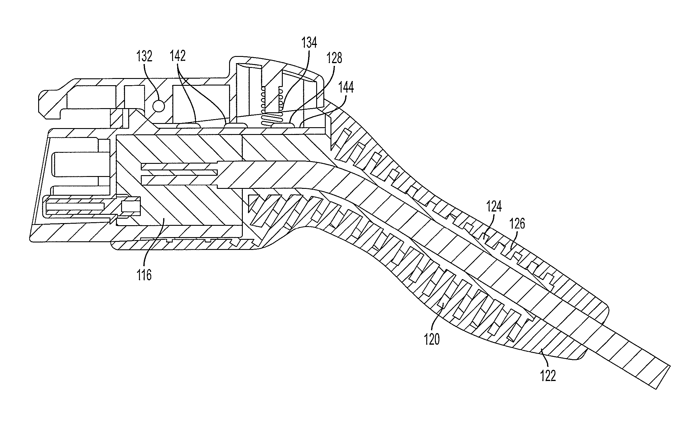
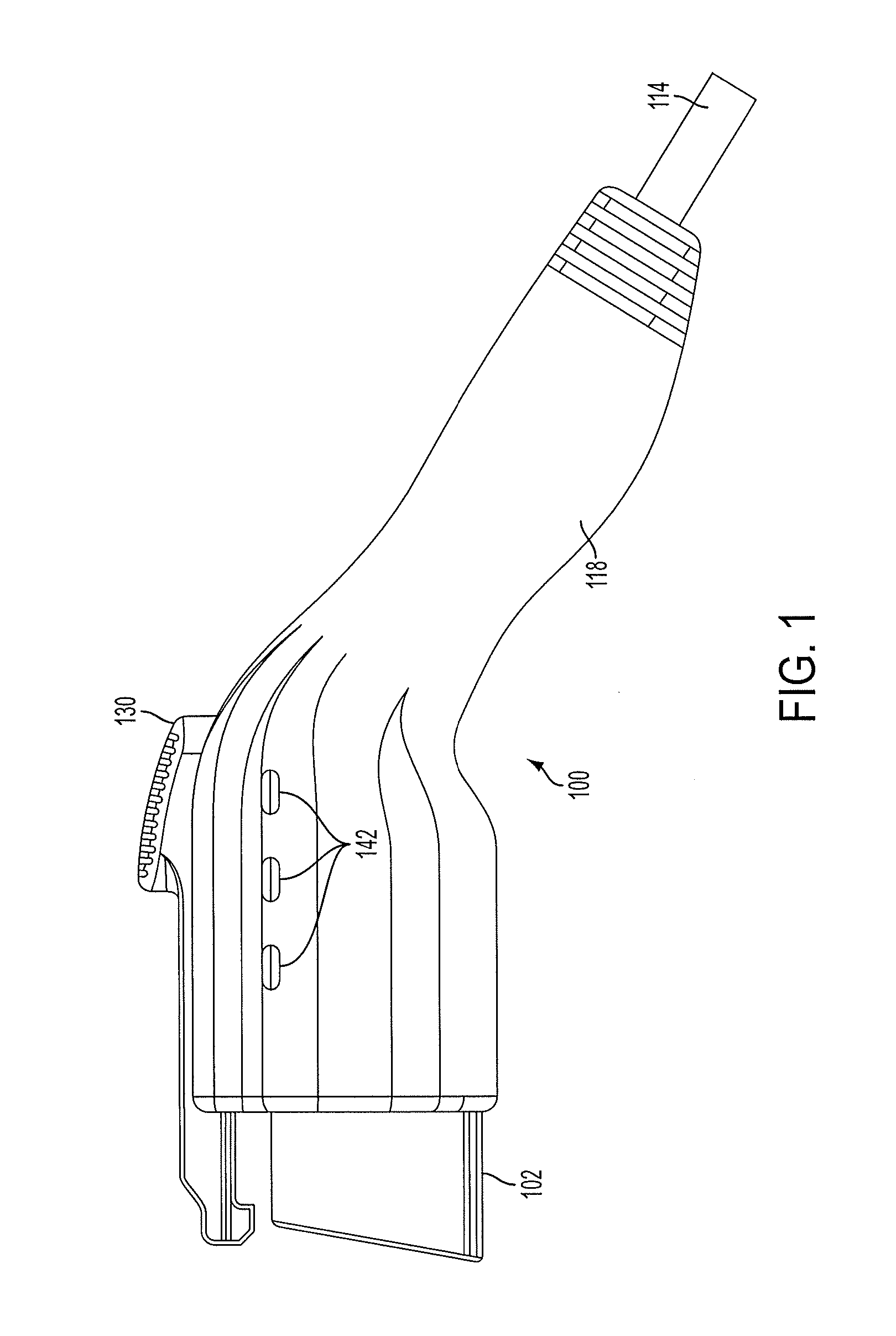
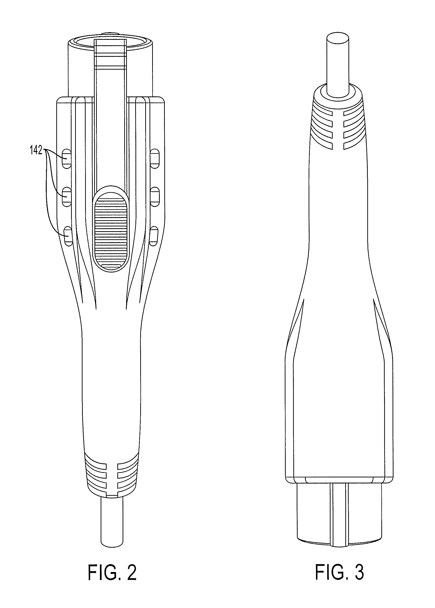
[0022]As shown in FIGS. 1-8, the connector 100 according to the preferred embodiment includes a connector front piece 102 with a plurality of pins 104, 106, 108, 110, 112. In the preferred embodiment, the connector front piece 102 and the pins 104-112 follow the standard SAE J1772. The pins 104-112 are electrically connected to a cable 114 at a location which is sealed inside of the connector front piece 102 with potting 116. A connector body 118 is formed over the connector front piece 102 and the cable 114 by a premold 120 and an overmold 122. The premold 120 and the overmold 122 are formed with ridges 124, 126 to increase the strength of the connector body 118. The connector body has a latch area 128 with a spring latch 130 having a pin 132 and a spring 134.

[0023]A first LED or other light 136 can be provided to act as a flash...


PUM

PropertyMeasurementUnit
areaaaaaaaaaaa
dielectric pottingaaaaaaaaaa
cross-linking adhesionaaaaaaaaaa

Abstract

In an electrical connector for an electric vehicle, the spring latch is not sealed; instead, the connector body has holes allowing water entering the spring latch mechanism to drain harmlessly out of the connector. A forward-facing LED or other light source acts as a flashlight. Once the connector is connected, the forward-facing LED is switched off, and a rear-facing LED or other light source is switched on to confirm that the connector is connected and capable of charging the vehicle. The connector is produced by overmolding in a three-layer configuration, where each layer is formed of a material having advantageous materials for that layer's position in the connector.

Description

REFERENCE TO RELATED APPLICATIONS[0001]The present application is a continuation-in-part of U.S. patent application Ser. No. 13 / 211,867, filed Aug. 17, 2011, currently pending, which claims the benefit of U.S. Provisional Patent Application No. 61 / 430,456, filed Jan. 6, 2011, and U.S. Provisional Patent Application No. 61 / 482,459, filed May 4, 2011. The present application is also a continuation-in-part of U.S. Design Pat. No. 29 / 382,230, filed Dec. 30, 2010, and of U.S. Design Pat. No. 29 / 408,312, filed Dec. 9, 2011, both of which are currently pending. The disclosures of the above-referenced applications are hereby incorporated by reference in their entireties into the present application.FIELD OF THE INVENTION[0002]The present invention is directed to an electrical connector for supplying power to an electric vehicle and more particularly to such a connector having improved resistance to water in the environment and improved user-friendliness.DESCRIPTION OF RELATED ART[0003]Elect...

Claims


Application Information

Patent Timeline
Patent Type & Authority Applications(United States)
IPC IPC(8): H01R24/28H01R43/16
CPCB60L11/1818H01R13/5227H01R13/6275H01R13/641H01R24/28Y10T29/49204Y02T10/7005Y02T90/14B60L2270/32B60L2270/34H01R2201/26B60L53/16Y02T10/70Y02T10/7072B60L50/50H01R13/52H01R13/62H01R13/6271H01R13/639
Inventor SEBALD, DAMIEN T.SMITH, BRIAN D.
Owner GENERAL CABLE TECH CORP
Learn More