Device and treatment chamber for thermally treating substrates

a technology for thermal processing and treatment chambers, which is applied in the direction of discharged materials, lighting and heating apparatus, furnace components, etc., can solve the problems of aggravated problems, damage to the coating (tears, inner stresses, etc.) and/or the substrate, and achieve the effect of reducing the heating or cooling power required to maintain a desired temperature, reducing the thermal load on the surroundings, and fast heating or cooling of the chamber interior

Inactive Publication Date: 2012-07-05
LEYBOLD OPTICS
View PDF4 Cites 16 Cited by
  • Summary
  • Abstract
  • Description
  • Claims
  • Application Information

AI Technical Summary

Benefits of technology

[0007]The treatment chamber is an enclosed space in an advantageous refinement of the invention. The substrate is introduced into the treatment chamber through a lock and conveyed and supported there with the aid of a transport arrangement. In such a thermal treatment chamber that can be sealed in a gas-tight fashion, the gas used for heating or cooling is advantageously supplied and removed in a closed gas circuit, which comprises the gas-guiding arrangement, the interior of the treatment chamber and the removal arrangement. This is particularly advantageous when the thermal treatment is carried out with the aid of gases that are reactive or toxic and therefore should not emerge into the surroundings. Furthermore, the proportion of heating or cooling power that could not be transferred from the gas to the substrate is not lost, but again flows to the gas-guiding arrangement via the removal arrangement and through the closed circuit. This affords the possibility of saving heating and cooling energy.
[0008]The removal arrangement is advantageously designed such that it allows a locally defined removal of the gas guided onto the substrate such that the gas emerging from an outlet opening of the gas-guiding arrangement is suctioned off in the direct vicinity of these outlet openings. Individual outlet openings (or groups of outlet openings) can be associated with removal domes that are shaped such that they remove the temperature-controlled gas emerging from these outlet openings in a targeted fashion. The heating or cooling gas thus only meets the substrate in a locally delimited region and is suctioned off locally before it can spread. This allows a very differentiated and controlled local heating or cooling of the substrate, and thermal gradients in the substrate can be avoided (or created in a targeted fashion). Suctioning off the gas directly in the vicinity of the outlet openings can furthermore prevent the gas from contacting the walls of the treatment chamber. This is particularly of great advantage if an industrial gas (e.g. a corrosive or toxic gas) is used for the convective heating or cooling, which gas can cause contamination or damage to the chamber walls. The removal arrangements thus act as shielding devices that protect the chamber walls from the influence of the gas.
[0012]The treatment chamber can be provided with a thermoinsulation shield for thermal shielding of the treatment chamber, the interior of which is intended to be heated or cooled during operation, against the surroundings. This can achieve faster heating or cooling of the chamber interior, more particularly of the substrate, and the heating or cooling power required to maintain a desired temperature can be reduced. By way of example, the thermoinsulation shield can be embodied as an outer chamber that can be sealed in a gas-tight fashion, more particularly as a vacuum chamber, and surrounds the inner chamber, in which the thermal processing of the substrate takes place, on all sides. The cavity situated between the inner and outer chamber insulates the (heated or cooled) inner chamber from the surroundings.
[0013]Alternatively, the thermoinsulation shield can be formed by a temperature-control arrangement—preferably arranged in the wall of the treatment chamber—that actively cools or heats the chamber wall. More particularly, the treatment chamber can be provided with a channel system that is integrated into the chamber wall and in which a liquid heating or cooling medium, for example an oil, circulates. If the treatment chamber is a heating chamber operated at high temperatures, the chamber walls can be cooled in a targeted fashion in order to minimize the thermal load on the surroundings, more particularly a vacuum chamber surrounding the heating chamber.

Problems solved by technology

However, at the same time, it must be ensured that the temperature gradients in the interior of the substrate are as low as possible during the heating and cooling, because otherwise transient or permanent deformations of the substrate occur and these can lead to damage to the coating (tears, inner stresses, etc.) and / or the substrate (deformations, formation of bubbles, bi-stable states of the substrate material etc.).
This problem is aggravated in the case of substrates made of materials with a low thermal conductivity, e.g. glass materials, because temperature differences within the substrate can only equilibrate slowly in these materials.

Method used


Image

  • Device and treatment chamber for thermally treating substrates
  • Device and treatment chamber for thermally treating substrates
  • Device and treatment chamber for thermally treating substrates

Examples


Embodiment Construction

[0018]In the drawings, mutually corresponding elements are denoted by the same reference sign. The drawings illustrate a schematic exemplary embodiment and do not reproduce any specific parameters of the invention. Furthermore, the drawings only serve to explain an advantageous embodiment of the invention and should not be interpreted as restricting the scope of protection for the invention.

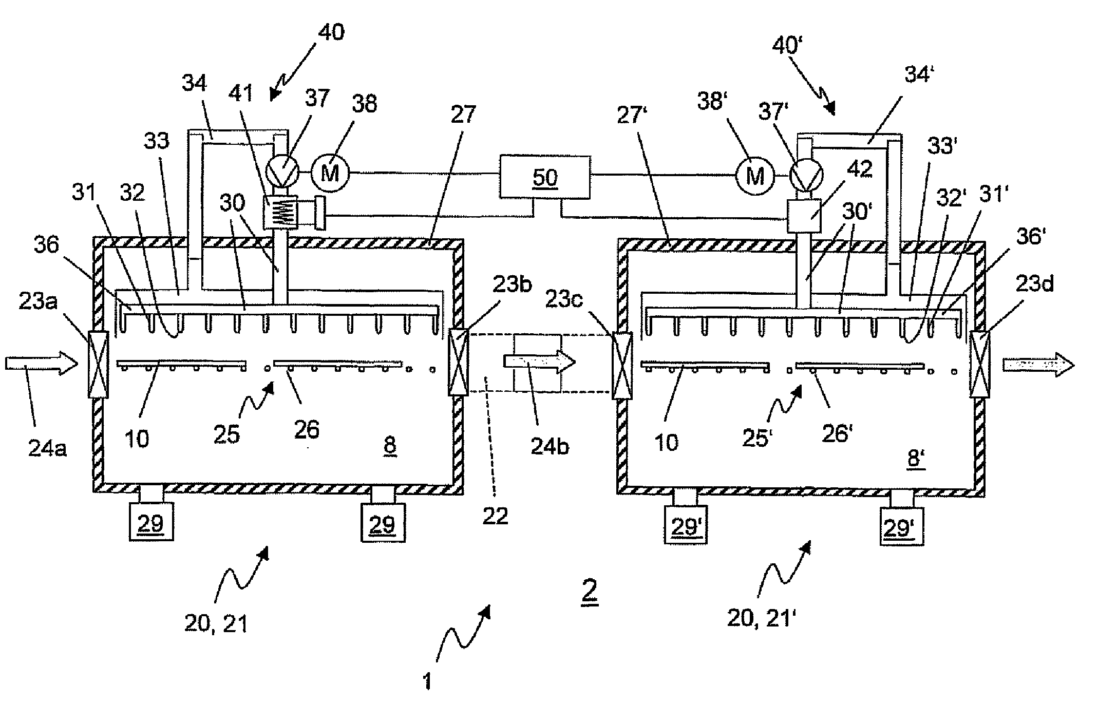
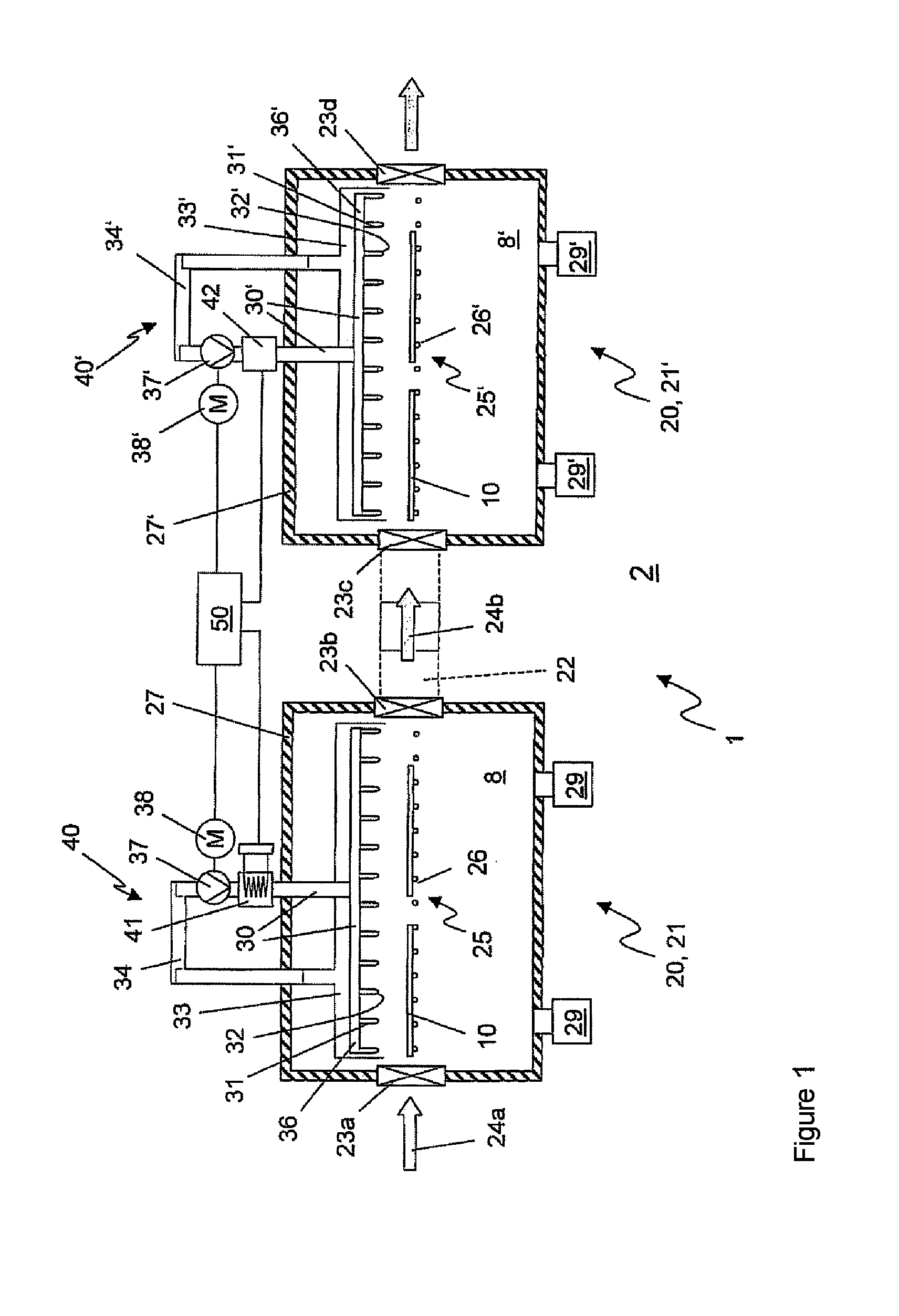
[0019]FIG. 1 shows a schematic sectional view of a device 1 for thermal processing of substrates 10. Here, the term “substrate” should be understood to be any object that needs to be processed or coated and / or already has been coated, that is to say both a (possibly pre-treated) substrate material as such and a substrate material with single or multiple coats. In the exemplary embodiment shown in the figures, the substrate is an areal workpiece made of glass, the surface area of which can range between a few square centimetres and a few square metres. “Thermal processing” should be understood to ...


PUM

PropertyMeasurementUnit
Temperatureaaaaaaaaaa
Poweraaaaaaaaaa
Flow rateaaaaaaaaaa

Abstract

A treatment chamber for thermal processing of an areal substrate including a transport arrangement for conveying and supporting the substrate during the thermal processing and a gas-guiding arrangement for convective heating or cooling of the substrate, where the gas-guiding arrangement has outlet openings, by means of which the temperature-controlled gas is guided onto the substrate, and where a removal arrangement is provided, by means of which the gases introduced into the treatment chamber via the gas-guiding arrangement can be removed in a targeted fashion, such that the treatment chamber can be embodied as a heat-treatment chamber or as a cooling chamber.

Description

TECHNICAL FIELD[0001]The invention relates to a treatment chamber for thermal processing of a substrate. The treatment chamber can be embodied as a heat-treatment chamber (heating chamber) or as a cooling chamber. The invention furthermore relates to a device with a heat-treatment and a cooling chamber for thermal processing of a substrate and also to a method for thermal processing of a substrate.BRIEF DISCUSSION OF RELATED ART[0002]Process steps are often required during the surface treatment of substrates, for example when applying transparent conducting oxide (TCO) layers during the production of flat-panel displays and solar cells or when coating substrates using CIGS thin-layer technology, during which steps the substrate (together with the coatings possibly applied to the substrate) is subjected to a thermal pre- and / or post-treatment. For this purpose, the substrate is typically heated to the desired temperature with the aid of a heat source, kept at this temperature for a p...

Claims


Application Information

Patent Timeline
IPC IPC(8): F27D15/02
CPCC03B27/0404C03B27/0417C03B27/044C03B29/025H01L21/6776F27B9/3005H01L21/67109H01L21/67173C03B29/08F27B9/30
Inventor NOVAK, EMMERICH MANFREDTRUBE, JUTTA
Owner LEYBOLD OPTICS
Why Eureka
Try Eureka