
Soft-magnetic, amorphous alloy ribbon and its production method, and magnetic core constituted thereby

a technology of amorphous alloy ribbon and soft-magnetic, which is applied in the direction of magnets, manufacturing tools, magnets, etc., can solve the problems of large speed of non-uniform magnetization change, large apparent power of relatively thin amorphous alloy ribbon, and low iron loss, and achieve high lamination factor. , the effect of low iron loss

Active Publication Date: 2012-06-21
HITACHI METALS LTD
View PDF1 Cites 19 Cited by
  • Summary
  • Abstract
  • Description
  • Claims
  • Application Information

AI Technical Summary

Benefits of technology

[0010]Accordingly, an object of the present invention is to provide a soft-magnetic, amorphous alloy ribbon having low iron loss and apparent power as well as a high lamination factor, its production method, and a magnetic core constituted by such soft-magnetic, amorphous alloy ribbon.SUMMARY OF THE INVENTION
[0011]As a result of intensive research in view of the above object, it has been found that in the formation of amorphous recesses in lines of dots by irradiating a surface of a soft-magnetic, amorphous alloy ribbon with laser beams in a transverse direction with predetermined longitudinal intervals, it is possible to reduce iron loss while suppressing increase in apparent power with a lamination factor kept high, by controlling the irradiation conditions of laser beams such that annular projections formed around the recesses are doughnut-shaped projections having smooth surfaces substantially free from splashes of the alloy melted by the irradiation of laser beams, that the height t2 of the annular projections is 2 μm or less, and that a ratio t1 / T of the depth t1 of the recesses to the thickness T of the ribbon is in a range of 0.025-0.18. The present invention has been completed based on such finding.
[0012]The soft-magnetic, amorphous alloy ribbon of the present invention is formed by a rapid quenching method, and has transverse lines of recesses formed on its surface by laser beams with predetermined longitudinal intervals, with a doughnut-shaped projection formed around each recess; the doughnut-shaped projections having smooth surfaces substantially free from splashes of the alloy melted by the irradiation of laser beams, and a height t2 of 2 μm or less; and a ratio t1 / T of the depth t1 of the recesses to the thickness T of the ribbon being in a range of 0.025-0.18, thereby having low iron loss and low apparent power.

Problems solved by technology

Large anomalous eddy current loss in this amorphous alloy is presumably due to the fact that magnetic domains in the amorphous alloy have large width, resulting in a high speed of domain wall displacement, and thus a large speed of the non-uniform magnetization change.
It has been found, however, that when deep recesses are formed at such a large irradiation energy density of laser beams that splashes are formed around the recesses, particularly a relatively thin amorphous alloy ribbon would suffer increase in apparent power (exciting VA) and decrease in a space factor despite the decreased iron loss.
Increase in the apparent power of the amorphous alloy ribbon results in larger sound noise when used for distribution transformers, etc.
Increase in the apparent power and decrease in the lamination factor have more serious problems on thinner amorphous alloy ribbons, because thinner amorphous alloy ribbons are more influenced by laser-scribed surface conditions than thicker amorphous alloy ribbons.
However, when laser pulses having as low energy as near 0.02 J / mm2 are projected to an amorphous alloy ribbon as thick as 65 μm, the resultant recesses are not fully deep relative to the thickness of the amorphous alloy ribbon, failing to obtain a sufficient iron loss-reducing effect.
However, because the molten portions are crystallized regions, the iron loss is not sufficiently reduced.

Method used


Image

  • Soft-magnetic, amorphous alloy ribbon and its production method, and magnetic core constituted thereby
  • Soft-magnetic, amorphous alloy ribbon and its production method, and magnetic core constituted thereby
  • Soft-magnetic, amorphous alloy ribbon and its production method, and magnetic core constituted thereby

Examples


example 1

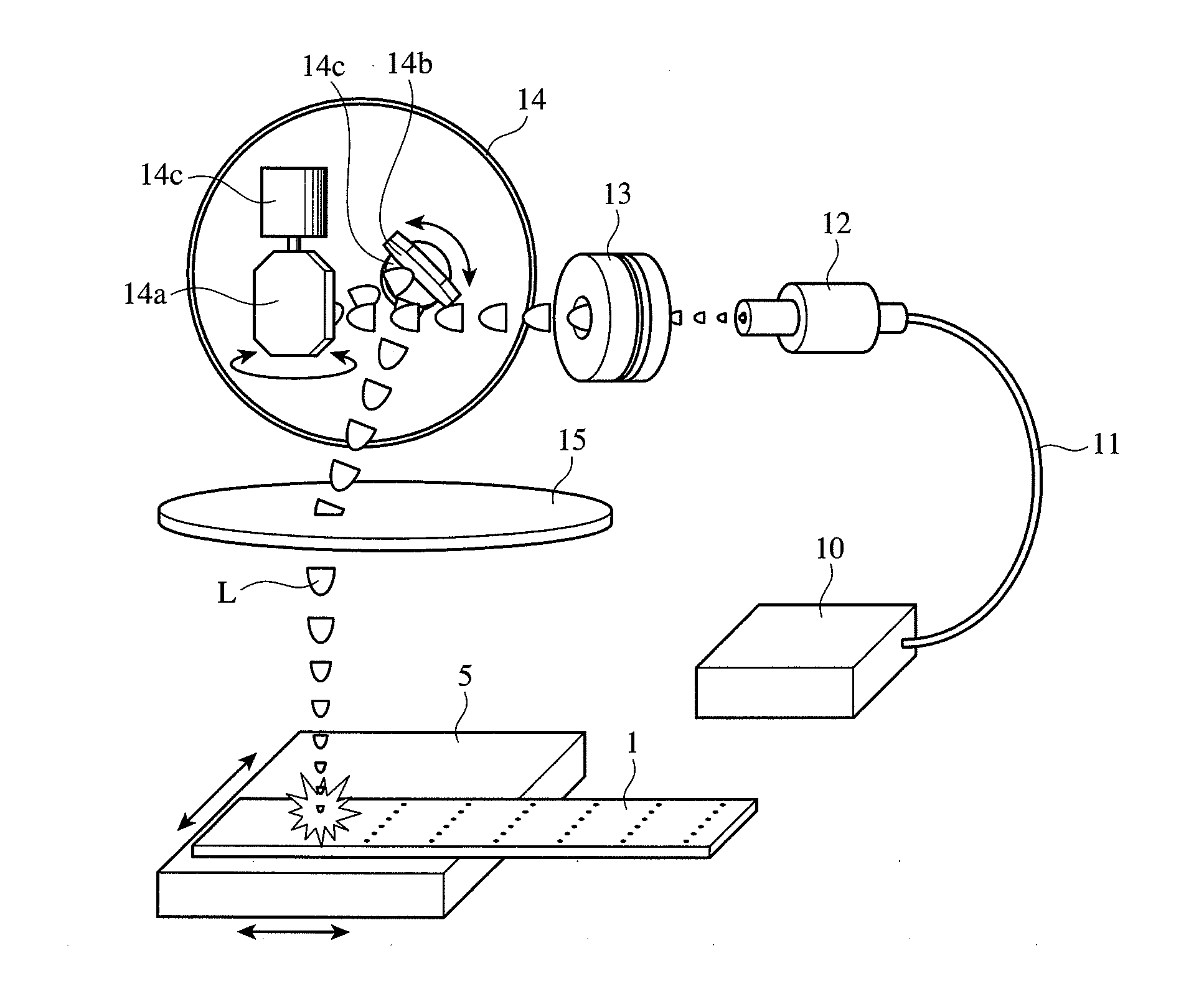
[0061]An amorphous alloy ribbon as wide as 5 mm and as thick as 23 μm having a composition comprising 11.5 atomic % of B, and 8.5 atomic % of Si, the balance being Fe and inevitable impurities, was produced by a single roll method in the air. A freely solidified surface of this alloy ribbon had reflectance R of 68.3% to light having a wavelength of 1000 nm. As shown in FIG. 1, the freely solidified surface of this amorphous alloy ribbon was scanned with laser beam pulses having a wavelength of 1065 nm, a pulse width of 550 ns and a beam diameter of 90 μm at an irradiation energy density of 2.5 J / cm2, which were sent from the fiber laser 10 via the galvanometer scanner (mirror) 14, to form transverse lines of recesses as shown in FIG. 3. The number density of recesses in transverse lines was 2 / mm, and the longitudinal intervals DL of the lines of recesses were 5 mm. The sizes of the recesses and annular projections surrounding them were as follows:

[0062]Recesses[0063]Diameter D1: 50 ...

example 2

[0071]With the irradiation energy density of laser beams having a wavelength of 1065 nm, a pulse width of 500 ns and a beam diameter of 60 μm changed, lines of recesses having various annular projection heights and recess depths were produced on the same amorphous alloy ribbon as in Example 1. FIG. 5 shows the relation between the irradiation energy density of laser beams and the height t2 of annular projections, and FIG. 6 shows the relation between the irradiation energy density of the same laser beams and the outer diameter D2 of the annular projections. As the irradiation energy density increased, the recesses 2 became deeper, and the annular projections 3 had larger outer diameters D2 and height with more molten alloy splashes. When the irradiation energy density was 5 J / cm2 or less, the annular projections 3 in a doughnut shape had heights t2 of 2 μm or less and outer diameters D2 of 90 μm or less. Of course, the heights t2 and outer diameters D2 of the doughnut-shaped project...

example 3

[0072]Some of the ribbons provided with recesses in Example 2 were cut to 120 mm, and heat-treated at 350° C. for 1 hour in a magnetic field of 1.2 kA / m oriented in the longitudinal direction of the ribbon. The resultant single-plate samples were measured with respect to iron loss P (W / kg) and apparent power S (VA / kg). FIG. 7 shows the relation between the height t2 of annular projections and the apparent power S at 50 Hz and 1.3 T. As is clear from FIG. 7, t2 of 2 μm or less provided a low apparent power S, but when t2 exceeded 2 μm, the apparent power S increased drastically. FIG. 8 shows the relation between the height t2 of annular projections and the iron loss P at 50 Hz and 1.3 T. As is clear from FIG. 8, the formation of recesses decreased the iron loss P, but t2 of more than 2 μm provided slightly increased iron loss P. As is clear from FIGS. 7 and 8, with the height t2 of annular projections in a range of about 2.5 μm or less (particularly in a range of 0.5-2.5 μm), the iro...


PUM

PropertyMeasurementUnit
Fractionaaaaaaaaaa
Lengthaaaaaaaaaa
Nanoscale particle sizeaaaaaaaaaa

Abstract

A soft-magnetic, amorphous alloy ribbon produced by a rapid quenching method, having transverse lines of recesses formed on its surface by laser beams with predetermined longitudinal intervals, with a doughnut-shaped projection formed around each recess; doughnut-shaped projections having smooth surfaces substantially free from splashes of the alloy melted by the irradiation of laser beams, and a height t2 of 2 μm or less; and a ratio t1 / T of the depth t1 of the recesses to the thickness T of the ribbon being in a range of 0.025-0.18, thereby having low iron loss and low apparent power.

Description

FIELD OF THE INVENTION[0001]The present invention relates to a soft-magnetic, amorphous alloy ribbon with low loss and apparent power and a high lamination factor and suitable for distribution transformers, high-frequency transformers, saturable reactors, magnetic switches, etc., its production method, and a magnetic core constituted by such soft-magnetic, amorphous alloy ribbon.BACKGROUND OF THE INVENTION[0002]Soft-magnetic, Fe- or Co-based, amorphous alloys produced by liquid quenching methods such as a single roll method, etc. are free from magnetocrystalline anisotropy because of no crystal grains, having small magnetic hysteresis loss, low coercivity and excellent soft magnetic properties. Because of these properties, amorphous alloy ribbons are used in magnetic cores for various transformers, choke coils, saturable reactors and magnetic switches, magnetic sensors, etc. Particularly, Fe-based, amorphous alloy ribbons have relatively high saturation magnetic flux densities Bs, l...

Claims


Application Information

Patent Timeline
IPC IPC(8): H01F3/04B32B3/30B23H1/00
CPCC22C38/02C22C45/02Y10T428/12389H01F41/0226Y10T29/49078H01F1/15341
Inventor YOSHIZAWA, YOSHIHITOITO, NAOKIKAZUI, SHINICHISASAKI, MAKOTO
Owner HITACHI METALS LTD
Learn More