Deicing method based on carbon/glass fiber hybrid textile

a carbon/glass fiber hybrid textile and deicing method technology, applied in the direction of ohmic-resistance heating, transportation and packaging, etc., can solve the problems of inconvenient and security risks to transportation, full closure, huge economic loss to a country, etc., to improve the whole mechanical behavior of the structure, improve the ability of directional strengthening, and improve the effect of anti-crack ability

Inactive Publication Date: 2012-05-31
SONG SHIDE
View PDF5 Cites 10 Cited by
  • Summary
  • Abstract
  • Description
  • Claims
  • Application Information

AI Technical Summary

Benefits of technology

[0006]Textile Reinforced Concrete (TRC) is a new high performance cementitious composite material consisting of multi-axial textile reinforcement made with advanced textile technology and fine-grained concrete. The warp and weft rovings of the textile are normally glass fiber rovings. The textile has excellent ability of directional strengthening and delaying crack. Due to the wonderful cor

Problems solved by technology

In winter, snow and ice on pavement, bridge and airport bring inconvenience and security risks to transportation, such as traffic jams, speed restriction, full closure of the highways, flight delays and even the closure of the airports due to the snow.
Besides, snow and ice also cause huge economic loss to a country.
Chloride deicing salt with advantages of low cost and good deicing performance has been widely used in the world, but the use of chloride has cause corrosion of steel bars in concrete, road surface denudation, environmental pollution and vegetation damages.
Electric cable heating system presents poor corrosion resistance of the

Method used


Image

  • Deicing method based on carbon/glass fiber hybrid textile
  • Deicing method based on carbon/glass fiber hybrid textile
  • Deicing method based on carbon/glass fiber hybrid textile

Examples


Embodiment Construction

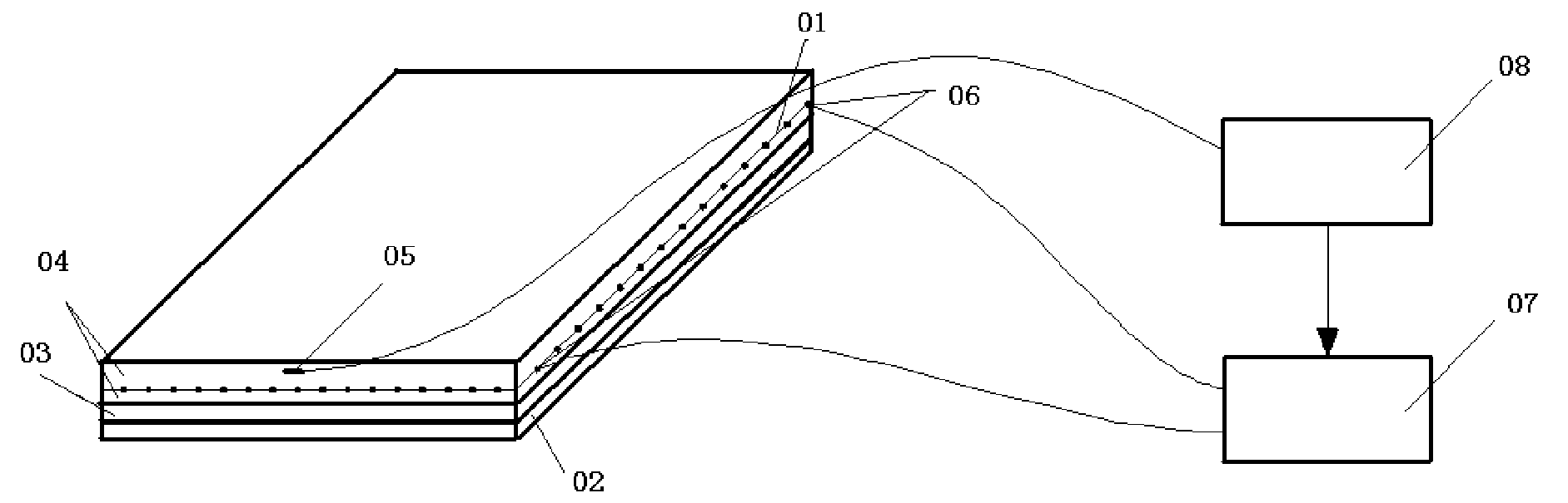
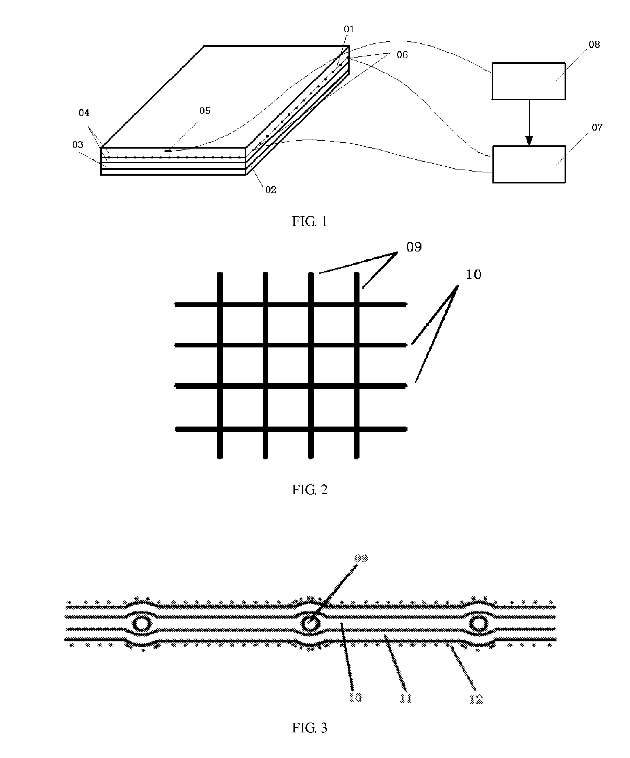
[0035]The present disclosure relates to a deicing method based on carbon / glass fiber hybrid textile 01, as shown in FIG. 1. Carbon / glass fiber hybrid textile 01 is shown in FIG. 2, with carbon fiber rovings 09 in warp direction and AR-glass fiber rovings 10 in weft direction. Here, carbon fiber rovings 09 are electric heating elements. The carbon / glass fiber hybrid textile 01 is treated with epoxy resin impregnating 11 and sand penetration 12, as shown is FIG. 3.

[0036]The Construction Process is as Follows:

[0037]As shown in FIG. 1, the bottom layer is thermal insulation layer 03 with thickness of 10˜30 mm, which is laid on the substrate 02 to reduce thermal loss and make full use of power.

[0038]As shown in FIG. 1, above the thermal insulation layer 03, a thermal conducting layer 04 is installed. The treated carbon / glass fiber hybrid textile 01 is tiled in the thermal conducting layer 04, with the warp carbon fiber rovings 09 parallel to the short side of the structure, Temperature s...


PUM


Abstract

The present disclosure relates to a deicing method based on carbon/glass fiber hybrid textile, with carbon fiber rovings in warp direction and AR-glass fiber rovings in weft direction; additionally, the mesh size of the textile is not less than 10 mm* 10 mm. The carbon/glass fiber hybrid textile treated with epoxy resin impregnating and sand penetration is embedded into thermal conducting layer, and carbon fiber rovings are wired to high power supply to turn electric energy into heat energy, which can melt ice and snow on the surface of thermal conducting layer when the surface temperature exceeds zero degree Celsius. In order to reduce thermal loss and make full use of thermal energy, thermal insulation layer is placed between thermal conducting layer and the substrate. The deicing temperature can be adjusted with designed temperature controller, which can optimize control parameters according to current surface temperature, wind speed, snow and ice thickness, environment temperature and expected deicing time. The carbon/glass fiber hybrid textile can realize uniform and rapid heating, and the method possesses reliable performance, strengthening and toughening substrate, low cost and long service life.

Description

CROSS-REFERENCE TO RELATED APPLICATIONS[0001]This application is the U.S. national phase application of PCT International Application No. PCT / CN2009 / 075201, filed on Nov. 29, 2009, which claims priority to China Patent Application No. CN200810229274.2, filed on Nov. 29 2008. The above application(s) is hereby incorporated herein by reference.TECHNICAL FIELD[0002]The present invention relates to a method for deicing based on carbon / glass fiber hybrid textile for transportation area to mitigate the impact of natural hazards.BACKGROUND OF THE INVENTION[0003]In winter, snow and ice on pavement, bridge and airport bring inconvenience and security risks to transportation, such as traffic jams, speed restriction, full closure of the highways, flight delays and even the closure of the airports due to the snow. Besides, snow and ice also cause huge economic loss to a country. Therefore, effective measures are in urgent need to eliminate snow and ice in time to keep the traffic safe and smoot...

Claims


Application Information

Patent Timeline
IPC IPC(8): B60L1/02
CPCE01C11/265H05B3/145H05B2214/02H05B2203/026H05B3/342
Inventor SONG, SHIDE
Owner SONG SHIDE
Why Eureka
Try Eureka