Interlocking Rubber Tiles For Playgrounds

a rubber tile and playground technology, applied in the field of protective padding, can solve the problems of long-term disability, affecting the overall effectiveness of protective padding, and the ground material can prove to be very unforgiving, so as to reduce the separation, curling and peeling of the edges.

Inactive Publication Date: 2012-05-24
UNITY CREATIONS
View PDF6 Cites 9 Cited by
  • Summary
  • Abstract
  • Description
  • Claims
  • Application Information

AI Technical Summary

Benefits of technology

[0013]It is still another object of the present invention to provide rubberized tiles which interlock with one another, and which include structure that acts as a reservoir for containing glue to adhesively join adjacent tiles together, and further include structure that allows excess glue to be removed from the reservoir.
[0014]It is yet a further object of the present invention to provide interlocking tiles that include structure which helps minimize separation, curling and peeling of the edges of the tiles.
[0015]It is yet another object of the present invention to provide interlocking tiles for use with playgrounds, rooftop surfaces and the like made from reprocessed or recycled rubber which overcome the inherent disadvantages of known tiles.

Problems solved by technology

Such injuries include head trauma, fractures and sprains, some leaving long term disability.
During incidents in which the child loses control or balance, the ground material can prove to be very unforgiving.
Unfortunately, the underlying ground material can affect the overall effectiveness of the protective padding.
While this conventional design provides means for effectively positioning and maintaining coverage of a concrete slab, if the same foam pad is placed on loose gravel or rocks, it will not be secured and may cause further personal injury from movement of the protective covering.
Additionally, when closed cell foam pads are placed on uneven surfaces such as gravel, the foam pads take the shape of the underlying surface, creating an uneven activity area that may provoke falls from tripping.
Conventional closed cell foam padding also tends to become slippery when wet from inclement weather or nearby sprinklers as water commonly pools on the flat surface thereof.
However, such conventional tiles do not interlock with one another and may separate, or buckle, leaving either an exposed area of the supporting surface on which the tiles are laid, or an uneven surface, which may cause injury to a child playing on the tiled surface.
Also, if conventional non-interlocking tiles are installed on a rooftop, they may be unsafe and may cause injury because of the potential flight characteristics of such tiles resulting from high wind conditions.
When conventional tiles are placed next to each other, even if they were somehow glued together, there may be a tendency for the tiles to curl at their edges, possibly caused by temperature fluctuations or use.
Such curling may result in an uneven surface and may cause injury to a person walking or running thereon.

Method used


Image

  • Interlocking Rubber Tiles For Playgrounds
  • Interlocking Rubber Tiles For Playgrounds
  • Interlocking Rubber Tiles For Playgrounds

Examples


first embodiment

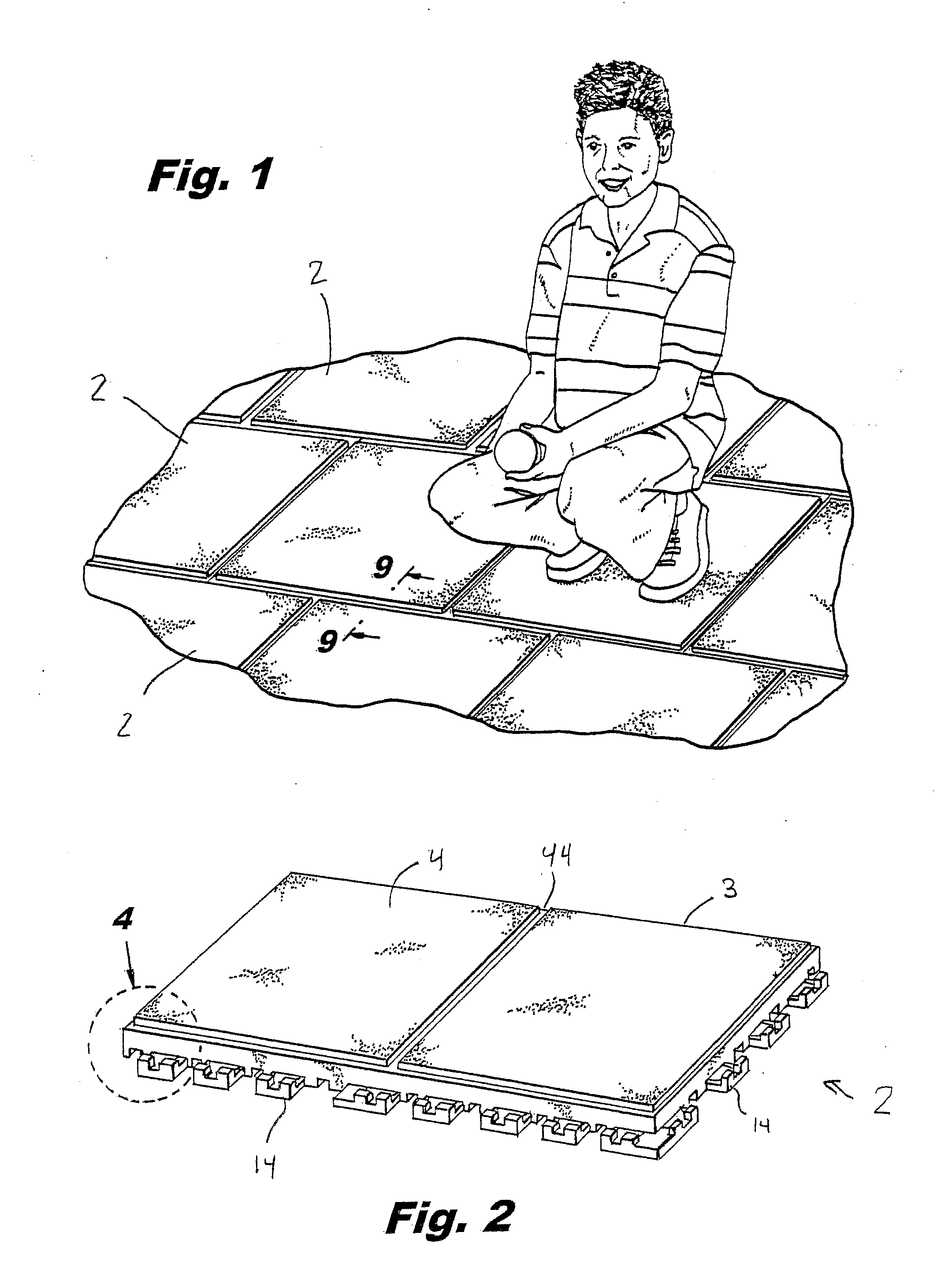
[0046]Referring to FIGS. 1-9 of the drawings, it will be seen that a rubber tile protective system constructed in accordance with the present invention includes a plurality of rubber tiles 2, each rubber tile 2 being interconnectable to another by a series of interlocking mechanisms integrated along the peripheral edges of each tile. The rubber tiles 2 may be selectively coupled by the interlocking mechanisms to one another to form a customizable protective surface of various proportion and size, depending on the specific application and area to be protected.

[0047]Each tile 2 may be formed in a plurality of shapes and sizes, but preferably is rectangular. The tile 2 includes a main body 3 residing generally in a plane and having a top surface 4 having a high coefficient of friction for providing sufficient traction to children and other users. The main body 3 of the tile 2 also includes an oppositely disposed bottom surface 6, the bottom surface 6 being laid on and resting on the gr...

second embodiment

[0056]However, in this second embodiment, the tile 2 includes one or more slots 17 (that is, elongated recesses or openings) formed in at least one lateral side thereof, and one or more elongated projections 15 formed on at least another lateral side of the tile 2 which is preferably situated opposite the side having the slot or slots 17 formed therein. In a preferred form, the tile 2 includes a plurality of slots 17 spaced apart from each other, each slot being positioned on a side of the tile between adjacent male connectors 14, as shown in FIG. 12 of the drawings. Alternatively, one or more elongated projections 15 may be situated on this side between the male connectors 14 instead of the slots 17.

[0057]Correspondingly, in this preferred form, the tile 2 includes a plurality of elongated projections 15 spaced apart from each other, each projection being positioned on a side of the tile that is preferably opposite the side having the slots 17, as shown in FIG. 13 of the drawings. ...


PUM

PropertyMeasurementUnit
areaaaaaaaaaaa
sizeaaaaaaaaaa
compositionaaaaaaaaaa

Abstract

A tile for covering an area which interlocks with an adjacent tile includes a main body having a top surface and a bottom surface disposed opposite the top surface. The main body has at least a first lateral side and a second lateral side. The tile includes a plurality of spaced apart male connectors situated on the first lateral side, and a plurality of spaced apart female receptacles situated on the second lateral side. The tile further includes a plurality of spaced apart slots and a plurality of spaced apart projections. Each slot is situated on either the first lateral side or the second lateral side of the main body inbetween either adjacent male connectors or adjacent female receptacles. Similarly, each projection is situated either on the first lateral side or the second lateral side of the main body inbetween either adjacent female receptacles or adjacent male connectors. The male connectors of the tile are engageable with female receptacles of an adjacent tile so that the tile may interlock with the adjacent tile. Also, the projections of the tile are receivable by slots of the adjacent tile to help prevent the tiles from curling or separating.

Description

CROSS-REFERENCE TO RELATED APPLICATIONS[0001]This application is a continuation-in-part of U.S. application Ser. No. 12 / 799,784, filed on Apr. 30, 2010, and entitled “Interlocking Rubber Tiles for Playgrounds”, the disclosure of which is incorporated herein by reference and on which priority is hereby claimed, which prior application is based on U.S. Provisional Application Ser. No. 61 / 215,087, which was filed on May 1, 2009, and is entitled “Interlocking Rubber Tiles For Playgrounds”, and U.S. Provisional Application Ser. No. 61 / 279,975, which was filed on Oct. 28, 2009, and is entitled “Interlocking Rubber Tiles For Playgrounds”, the disclosure of each of which is hereby incorporated by reference and on which priority is hereby claimed.BACKGROUND OF THE INVENTION[0002]1. Field of the Invention[0003]This invention generally relates protective padding and more particularly relates to recycled protective tiling.[0004]2. Description of the Prior Art[0005]The most common injuries at re...

Claims


Application Information

Patent Timeline
Patent Type & Authority Applications(United States)
IPC IPC(8): E04B5/48E04B5/00
CPCE01C5/18E01C2201/12E01C13/045
Inventor PRINZ, GEORGE H.WASHBURN, BRUCEPRINZ, ERICK B.
Owner UNITY CREATIONS
Why Eureka
Try Eureka