Control valve trim assembly

Active Publication Date: 2019-04-04
FISHER CONTROLS INT LLC
View PDF6 Cites 1 Cited by
  • Summary
  • Abstract
  • Description
  • Claims
  • Application Information

AI Technical Summary

Benefits of technology

The patent describes a new lattice structure for a trim assembly used in fluid flow applications. The structure is made using gyroids or gyroid-like surfaces, which results in arcuate surfaces that reduce pressure and turbulence in the fluid flow. This reduces noise and the likelihood of cavitation. The structure also provides a consistent pressure reduction as the fluid flow moves through the assembly. Overall, the patent describes a new design that improves the performance of trim assemblies in fluid flow applications.

Problems solved by technology

However, drilled hole cages are very cumbersome, time consuming, and costly to produce.
However, with drilled holes through a solid cage, creating passages having a non-linear flow path or having a variable cross-sectional area is not possible.

Method used


Image

  • Control valve trim assembly
  • Control valve trim assembly
  • Control valve trim assembly

Examples


Embodiment Construction

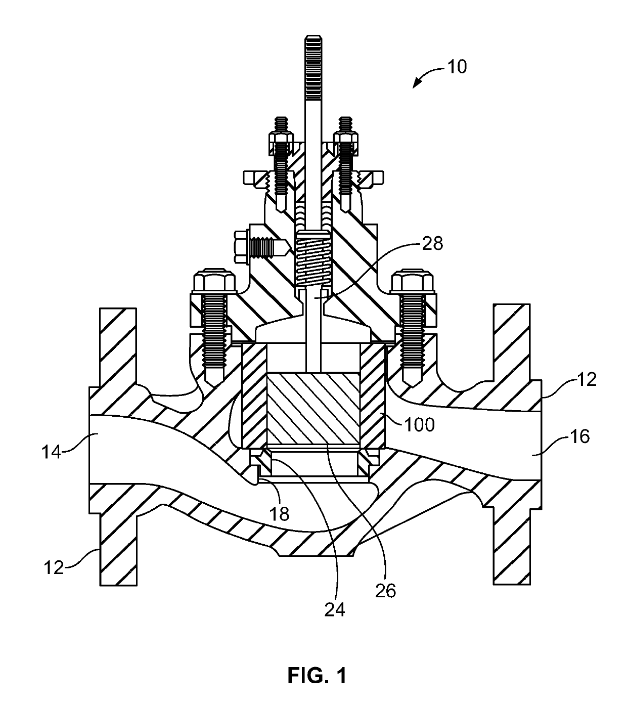
[0043]Referring to FIG. 1, an example sliding stem control valve 10 is shown. Control valve 10 generally includes a valve body 12 having an inlet 14, an outlet 16, and a passageway 18 disposed between inlet 14 and outlet 16. A valve seat 24 is disposed in passageway 18 between inlet 14 and outlet 16 and a trim assembly 100, such as a cage, is disposed within valve body 12 adjacent valve seat 24. A fluid control member, such as valve plug 26, is positioned within valve body 12 and is disposed within trim assembly 100. Valve plug 26 interacts with the valve seat 24 to control fluid flow through valve body 12, such that valve plug 26 is movable between a closed position in which it sealingly engages valve seat 24 and an open position in which it is spaced away from valve seat 24. A stem 28 is connected to valve plug 26 at one end and to an actuator at another end. The actuator controls movement of valve plug 26 within trim assembly 100, which in this example is positioned adjacent valv...


PUM


Abstract

A control valve has a trim assembly to condition the flow of fluid through the control valve and, in some applications, to provide guidance for a valve plug. The trim assembly has a lattice structure formed of a plurality of triply periodic surfaces that form a plurality of passages that extend between an inner surface of the circumferential wall and an outer surface of the circumferential wall.

Description

CROSS-REFERENCE TO RELATED APPLICATIONS[0001]This application claims priority to U.S. Provisional Patent Application No. 62 / 566,118, entitled “Control Valve Trim Assembly” and filed Sep. 29, 2017, the entire disclosure of which is hereby incorporated by reference herein.FIELD OF THE DISCLOSURE[0002]This disclosure relates generally to control valves and, more particularly, to trim assemblies for control valves.BACKGROUND[0003]In typical control valves, a trim assembly, such as a valve cage, may be used to condition the flow of fluid through the control valve, reduce noise, cavitation, and turbulence through the control valve, and in some applications can also be used to provide guidance for a fluid control member or valve plug as the valve plug moves from a closed position in which the valve plug sealingly engages a valve seat to an open position in which the valve plug is disposed away from the valve seat. When the control valve is in the open position, fluid flows from a valve inl...

Claims


Application Information

Patent Timeline
IPC IPC(8): F16K47/08F16K3/24
CPCF16K47/08F16K3/246F16K1/32F16K1/36F16K27/02F16K47/02F16L55/02B33Y80/00
Inventor EILERS, DANIEL J.MCNULTY, KYLE THOMAS
Owner FISHER CONTROLS INT LLC
Why Eureka
Try Eureka