
Method and Apparatus for Measuring a Structure on a Substrate, Computer Program Products for Implementing Such Methods and Apparatus

a technology of structure and substrate, applied in the direction of photomechanical apparatus, instruments, material analysis by optical means, etc., can solve the problems of large computational tasks, inability to accurately measure the structure on the substrate, and the risk of false matching of parameter sets that do not correspond to the measured substrate, so as to reduce the number of degrees of freedom in the model. , the effect of improving the tool for measuring

Active Publication Date: 2012-05-17
ASML NETHERLANDS BV
View PDF3 Cites 105 Cited by
  • Summary
  • Abstract
  • Description
  • Claims
  • Application Information

AI Technical Summary

Benefits of technology

The present invention provides an effective system and method for measuring structures on a substrate by reconstruction methods. The invention reduces the degrees of freedom in the model without compromising accuracy, by imposing relationships among a subset of the variable parameters and applying constraints to reduce the number of degrees of freedom. The invention also includes a method for generating a model recipe by designating which parameters will be treated as fixed and which parameters will be treated as variable, and applying the constraint in the generation of the candidate model structures to reduce the number of degrees of freedom in the model without treating the parameters of the subset as fixed. The invention further provides an inspection apparatus for measuring parameters of a structure on a substrate, and computer program products for causing a processor to implement the methods and apparatuses.

Problems solved by technology

Even with a handful of parameters, the size of computational tasks quickly becomes very large, for example by raising the number of library samples unacceptably.
It also raises the risk of falsely matching parameter sets that do not correspond to the measured substrate.
Unfortunately, fixing a parameter to a value that is not identical to what is in the measured structure will distort the matching process so that inaccuracy arises in floating parameters, which can be the parameters of most interest.
The recipe is therefore a delicate compromise between accuracy and practicality of computation.

Method used


Image

  • Method and Apparatus for Measuring a Structure on a Substrate, Computer Program Products for Implementing Such Methods and Apparatus
  • Method and Apparatus for Measuring a Structure on a Substrate, Computer Program Products for Implementing Such Methods and Apparatus
  • Method and Apparatus for Measuring a Structure on a Substrate, Computer Program Products for Implementing Such Methods and Apparatus

Examples


first example

LINEAR CONSTRAINT

[0116]A first example for illustrating the principles and benefits of these more generic conditions is a situation where the model contains two correlated parameters. FIG. 8, according to an embodiment of the present invention, shows an example in which the structure of target 30 comprises a substrate 800 with first and second layers 802, 804 formed thereon. First layer 802 has a thickness or height d1 and refractive index n1. Second layer 804 has a height d2 and refractive index n2. Another property of the structure is the sum height of the two layers, labeled dtot. The sum dtot of the two parameters can be made a parameter, and can be determined by any reasonably accurate model with good certainty. The refractive indices, for the sake of this example, are extremely close in value, however. Therefore it will be understood that any optical measurement technique will have difficulty resolving the parameters d1 and d2 individually.

[0117]Referring to FIG. 9(a), accordi...

second example

LINEAR CONSTRAINT

[0122]FIG. 10, according to an embodiment of the present invention, illustrates a second example of the application of linear constraints for improved model recipes. In this case, two generic parameters p1 and p2 are involved. Horizontal and vertical axes correspond to the deviations of these parameters, rather than their absolute values. The uncertainty (noise) in this example is well below the allowed parameter ranges, so that no rectangular bounding box is seen within the diagram. Here, a useful piece of information for the recipe optimization is that we are only interested in measuring one of the parameters, p1. As before, p1 and p2 are correlated so that floating both parameters would give a large uncertainty, while fixing p2 would introduce an unnecessarily large error in p1. The inventors have recognized that a constraint, for example a linear constraint 910 is still possible in many such situations, which will reduce the degrees of freedom in the model and i...

example results

[0126]FIG. 11, according to an embodiment of the present invention, illustrates a complex target structure 30 which for the sake of experiment was formed in 75 separate fields over a 300 mm substrate in a focus-exposure matrix (FEM) process. As is well known, a non-random FEM process is designed to vary parameters of the lithographic steps in a systematic and known way across fields of a substrate such as a silicon wafer. In this target structure, layers A through G are formed in a stack on a substrate 960. The top layer G is patterned using the lithographic apparatus and has shape parameters H_G, MCD_G and SWA_G similar to features 702 in FIG. 7. These three were defined as the parameters of interest. Each underlying layer A to F has its own height (H_A etc.) and material properties. For the purposes of experimentation, nominal values for all heights are known, but only layer A is fixed. Material properties such as refractive index were also fixed. This leaves 10 floating parameter...


PUM


Abstract

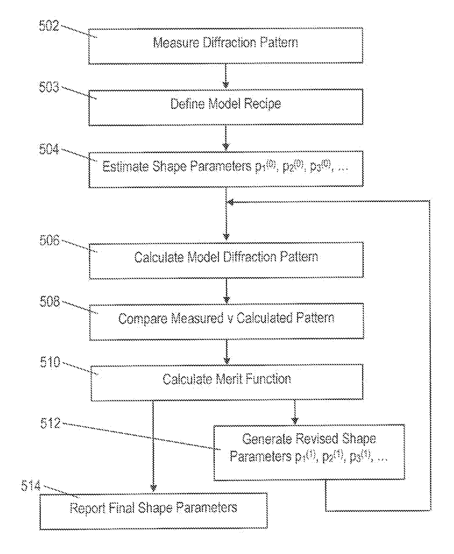
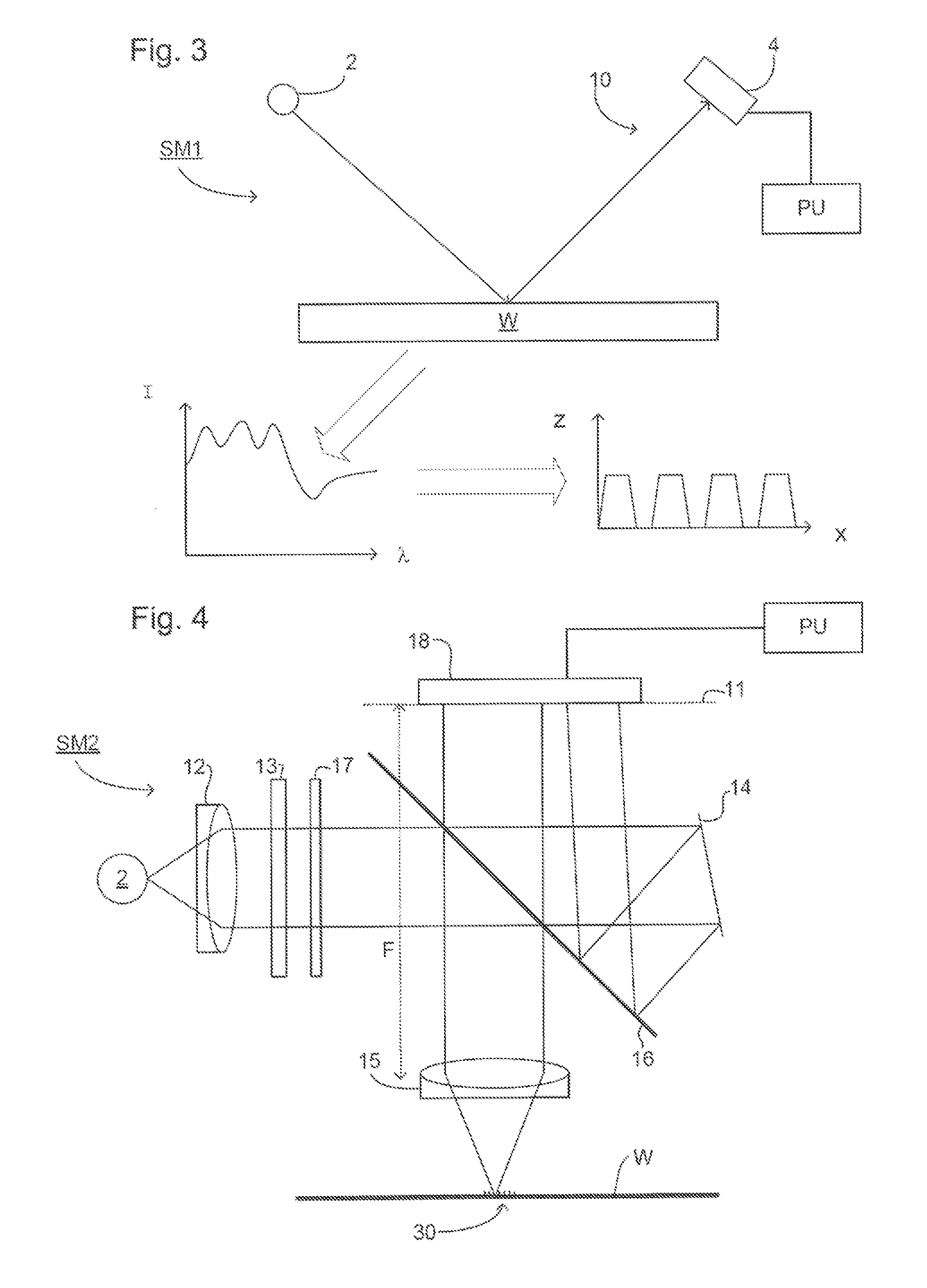
Diffraction models and scatterometry are used to reconstruct a model of a microscopic structure on a substrate. A plurality of candidate structures are defined, each represented by a plurality of parameters (p1, p2, etc.)). A plurality of model diffraction signals are calculated by simulating illumination of each of the candidate structures. The structure is reconstructed by fitting one or more of the model diffraction signals to a signal detected from the structure. In the generation of the candidate structures, a model recipe is used in which parameters are designated as either fixed or variable. Among the variable parameters, certain parameters are constrained to vary together in accordance with certain constraints, such as linear constraints. An optimized set of constraints, and therefore an optimized model recipe, is determined by reference to a user input designating one or more parameters of interest for a measurement, and by simulating the reconstruction process reconstruction. The optimized model recipe can be determined automatically by a parameter advisor process that simulates reconstruction of a set of reference structures, using a plurality of candidate model recipes. In the generation of the reference structures, restrictions can be applied to exclude unrealistic parameter combinations.

Description

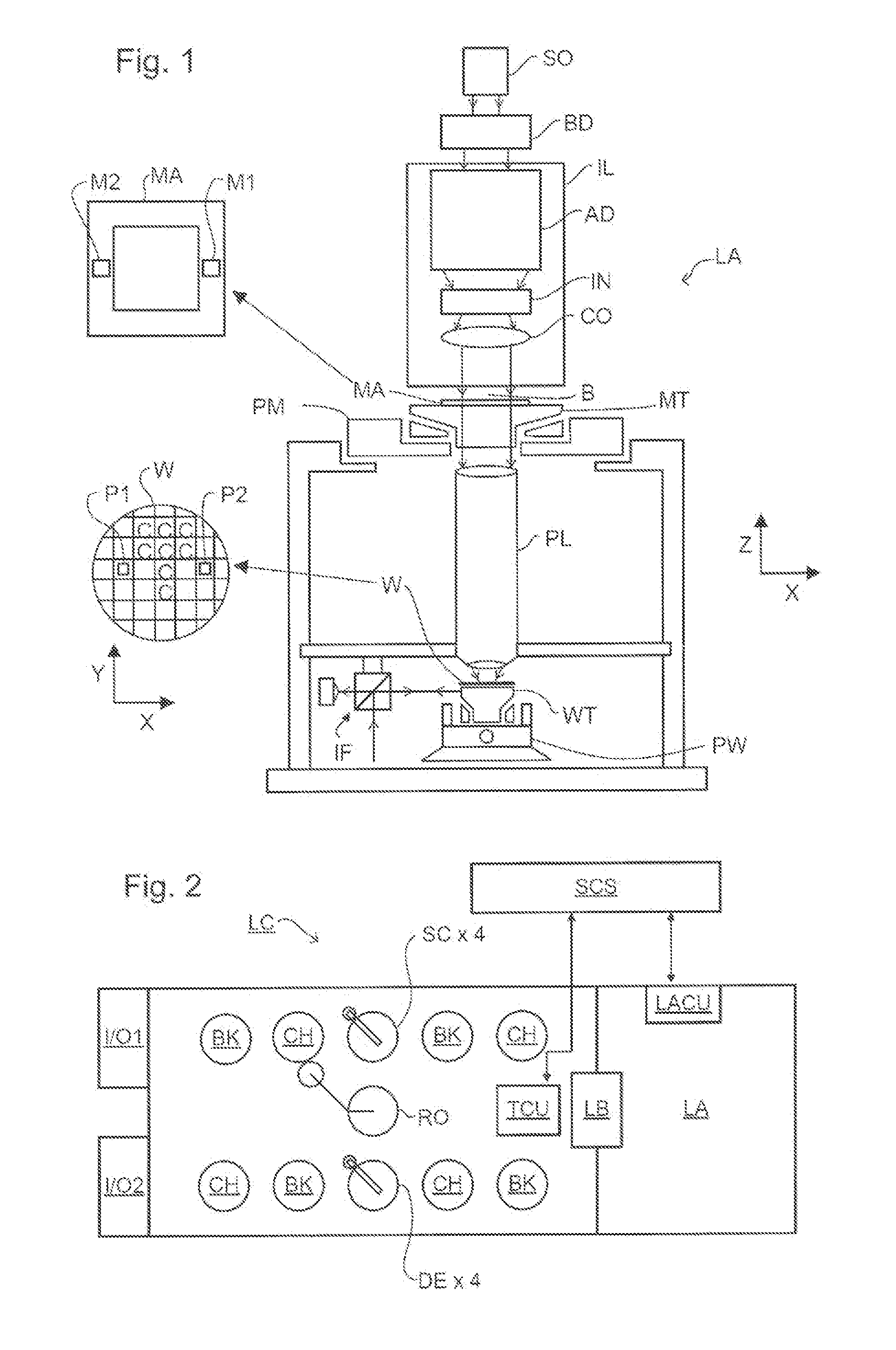
CROSS REFERENCE TO RELATED APPLICATIONS[0001]This applications claims benefit under 35 U.S.C. 119(e) to U.S. Provisional patent Application No. 61 / 351,527, filed, Jun. 4, 2010, which is incorporated by reference herein in its entirety.BACKGROUND[0002]1. Field of the Invention[0003]The present invention relates to methods and apparatus for measuring a structure on a substrate. The invention can be applied for example in model based metrology of microscopic structures, for example to assess critical dimensions (CD) or overlay performance of a lithographic apparatus.[0004]2. Related Art[0005]A lithographic apparatus is a machine that applies a desired pattern onto a substrate, usually onto a target portion of the substrate. A lithographic apparatus can be used, for example, in the manufacture of integrated circuits (ICs). In that instance, a patterning device, which is alternatively referred to as a mask or a reticle, can be used to generate a circuit pattern be formed on an individual...

Claims


Application Information

Patent Timeline
Patent Type & Authority Applications(United States)
IPC IPC(8): G06F17/50
CPCG03F7/70483G03F7/70491G03F7/70633G03F7/70625G03F7/705G03F7/20G01N21/956
Inventor ABEN, MARIA JOHANNA HENDRIKACRAMER, HUGO AUGUSTINUS JOSEPHWRIGHT, NOELLE MARTINAALVAREZ SANCHEZ, RUBENSLOB, MARTIJN JAAP DANIEL
Owner ASML NETHERLANDS BV
Learn More