Lighting appliance and process for manufacturing the same

a technology for lighting appliances and manufacturing processes, applied in the field of lighting appliances, can solve problems such as difficulty in providing lighting appliances, and achieve the effects of good shockproof, good compatibility with particulates, and good diffusion of particulates

Inactive Publication Date: 2012-05-17
SUZUDEN CORP +1
View PDF13 Cites 17 Cited by
  • Summary
  • Abstract
  • Description
  • Claims
  • Application Information

AI Technical Summary

Benefits of technology

[0026]Since said particulate of silicon dioxide is a spherical particle with a diameter of from 10 to 30 nm, and these particulates agglomerated to result in said agglomerates of said highly-diffusible silica particulates each having a diameter of from 100 to 400 nm, which is a bulky agglomerate. Because of such a structure of the agglomerate of the highly-diffusible silica particulates, light diffusion in the light illuminating member can be securely caused.
[0027]In addition, since the light-permeable matrix substance is a light-permeable silicon resin, it has good compatibility with the particulates and gives good diffusion of the particulates. Especially, when highly-diffusible silica is used and mixed as said particulates, homogeneous diffusion of the particulates can be obtained and provision of a lighting appliance provided with excellent shockproof can be achieved.
[0028]Further, in the lighting appliance according to the present invention, the substrate mounted with a light emitting diodes is connected with wires, and said wires, said substrate and said light emitting diodes are sealed off by molding in one united body with a synthetic resin material, to which particulates capable of diffusing light irradiated from the light emitting diodes. Since the lighting appliance of the invention is constituted as described above, it can be provided as a lighting appliance which has excellent waterproof, dustproof, shockproof and anti-pressure properties.
[0029]Further, since said substrate is jointed with a heat-discharging member, heat can be discharged even though the light emitting diod...

Problems solved by technology

However, because of the property of light emitted by a light emitting diode irradiates one direction only, it has been difficult to provide lighting appliances which can satisfy appropriate light directivity and light-diffusing property.[Patent Document 1] Japanese Unexamined Patent Application Publication No. 1994-163132[Patent Document 2] Japanese Unexamined Patent App...

Method used


Image

  • Lighting appliance and process for manufacturing the same
  • Lighting appliance and process for manufacturing the same
  • Lighting appliance and process for manufacturing the same

Examples


first embodiment

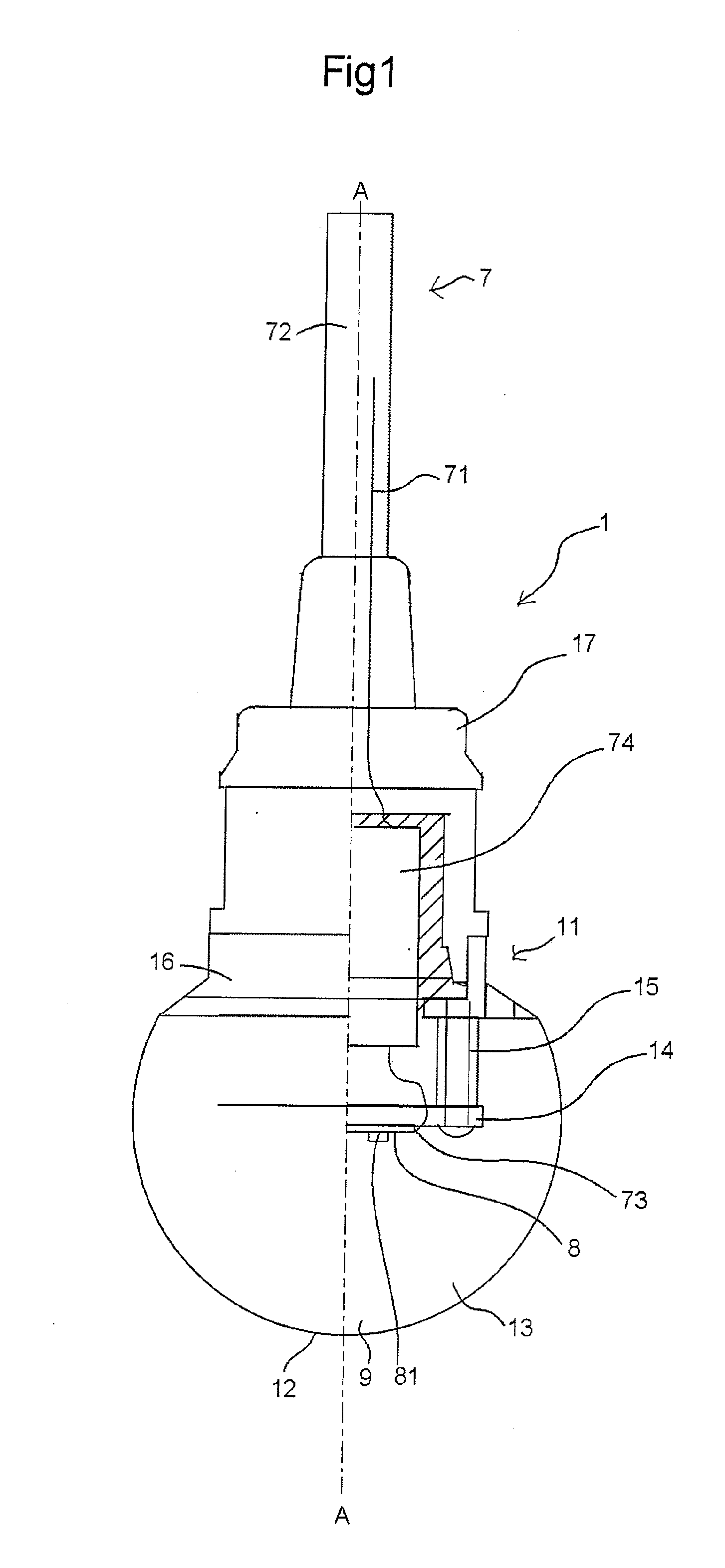
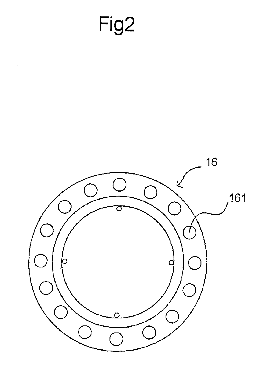
[0053]The lighting appliance according to the first embodiment of the present invention is shown in FIGS. 1 and 2. The lighting appliance according to the first embodiment includes light emitting diodes 81 as a light emitting element and a lighting appliance main body 11 including a light illuminating member 13 which seals off said light emitting diodes, and the lighting appliance main body 11 is connected with a cable 7. The lighting appliance main body 11 includes a substrate 8 mounted with light emitting diodes 81, wires 71 to be connected with the substrate 8, and a light illuminating member 13 formed with a synthetic resin material 9 mixed with light-diffusing particulates, said synthetic resin material seals off them in one united body to form the light illuminating member.

[0054]Specifically, a plurality of light emitting diodes 81 are mounted to the front surface of the substrate 8, and a pair of wires 71 are connected to the substrate 8 in order to cause said light emitting ...

second embodiment

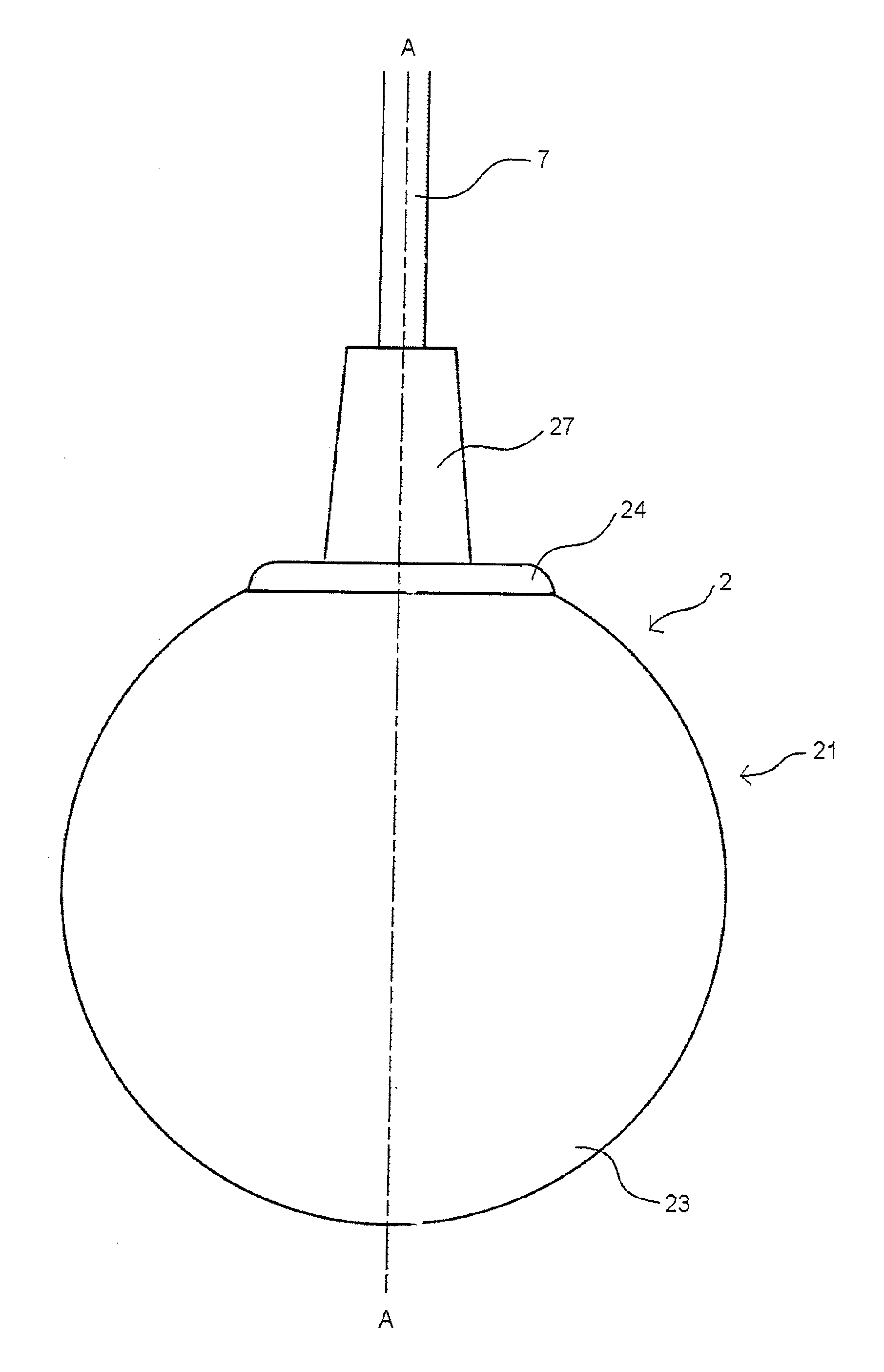
[0063]FIG. 4 is a side view of the lighting appliance according to the second embodiment of the present invention, and FIG. 5 is a cross-sectional view taken along A-A line of the lighting appliance shown in FIG. 4. The lighting appliance 2 according to the second embodiment also includes a lighting appliance main body 21, in which light emitting diodes 81 as a light emitting element and a light illuminating member 23 which seals off said light emitting diodes are included, and a cable 7 is connected with the lighting appliance main body 21. The light illuminating member 23 is formed with a synthetic resin material 9 which is used to seal off the substrate 8 to which a light emitting diode 81 is mounted, and the synthetic resin material 9 is prepared by mixing highly-diffusible silica as the light-diffusible particles to a light-permeable silicon resin having a certain elasticity, similarly to the first embodiment.

[0064]Specifically, a plurality of light emitting diodes 81 are mount...

third embodiment

[0071]In FIG. 6 and FIG. 7, a variation of the spherical lighting appliance according to the third embodiment is shown. FIG. 6 is a cross-sectional view of the lighting appliance according to the third embodiment taken in the vertical direction, and FIG. 7 is a cross-sectional view of the lighting appliance shown in FIG. 6 taken along B-B line.

[0072]The lighting appliance 3 according to the third embodiment also includes a lighting appliance main body 31 in which light emitting diodes 81 as a light emitting element and a light illuminating member 23 to seal off the light emitting diodes are included, and a cable 7 is connected to the lighting appliance main body 31. Further, the light illuminating member 33 is formed with a synthetic resin material 9 which seals off a substrate 8 mounted with light emitting diodes 81. The synthetic resin material 9 is prepared, similarly to the first embodiment, by mixing highly-diffusible silica as light-diffusing particulates to a light-permeable ...


PUM

PropertyMeasurementUnit
Diameteraaaaaaaaaa
Diameteraaaaaaaaaa
Electrical conductoraaaaaaaaaa

Abstract

The object of the present invention is to provide lighting appliances of various shapes, which use light emitting diodes as a light source, having excellent light directivity, light-diffusing property, durability and shock-proof property.
The lighting appliance 1 according to the present invention is constituted by including a light illuminating member 13 formed by sealing off a substrate 8 mounted with light emitting diodes 81 therein with a synthetic resin material 9 prepared by mixing particulates 92 capable of diffusing light irradiated from the light emitting diodes 81 to the matrix substance 91.

Description

1. FIELD OF INVENTION[0001]The present invention relates to a lighting appliance and a process for manufacturing the same, particularly to a lighting appliance which employs a light emitting diode as the light source and has excellent light-diffusion property.2. PRIOR ART[0002]In the past, for interior lighting, and exterior lightings, particularly for lighting during construction works, a lighting appliance, like a socket 101 as shown in FIG. 21, comprising an electric light bulb with a filament (not shown) to be screwed into a socket body 102 connected to a cable 103 has been used for a long time. In recent years, however, light emitting diodes have been used as a light source for lighting appliances because of their durability and less energy consumption.[0003]However, because of the property of light emitted by a light emitting diode irradiates one direction only, it has been difficult to provide lighting appliances which can satisfy appropriate light directivity and light-diffu...

Claims


Application Information

Patent Timeline
IPC IPC(8): F21V7/22B29C45/14
CPCF21S8/04F21S8/061F21Y2101/02F21V21/03F21V31/04F21V3/0445F21Y2115/10F21V3/0625
Inventor KOBAYASHI, SHINOBUKAWASHIMA, HIROAKI
Owner SUZUDEN CORP
Why Eureka
Try Eureka