
Movement sensor and system for establishing a movement profile

a movement sensor and movement technology, applied in the field of movement sensors and systems, can solve the problems of affecting the accuracy of the movement sensor, the patient may not be technically adept, and the operation of the button or the operation selection via the menu may be difficult, so as to increase the reliability of the movement sensor and reduce the internal resistance

Inactive Publication Date: 2012-05-17
ROBERT BOSCH GMBH
View PDF3 Cites 23 Cited by
  • Summary
  • Abstract
  • Description
  • Claims
  • Application Information

AI Technical Summary

Benefits of technology

[0010]In one particularly preferred specific embodiment of the movement sensor according to the present invention, an automatic change between various operating modes is provided, the particular operating mode relating to different environmental conditions. The various operating modes are preferably an operating mode for movements in the air and an operating mode for movements in water. This means that by changing over these operating modes, it is possible to differentiate between a movement in air and a movement in water, i.e., in particular swimming. The corresponding movement or acceleration signals are analyzed in accordance with a movement in air, i.e., in particular walking, standing, sitting, lying down, etc., and a movement in water, i.e., in particular swimming. Exercises in water play a large role within the scope of medical rehabilitation. For many patients, in particular also the chronically ill or older persons, a movement in water represents a very suitable form of movement in order to be physically active. The movement sensor according to the present invention is suitable in a particularly advantageous way for detecting the activity in the water and for taking the activity in water into consideration within the scope of a longer-term movement profile. In this case, the acceleration sensor may differentiate between different environmental conditions, i.e., in particular between air and water, so that the acceleration sensor may automatically select the particular suitable operating mode or accordingly change to the operating mode. Without a change of the operating mode from air to water, an activity during swimming would be incorrectly interpreted, for example, a backstroke would be interpreted as lying down. It is therefore provided according to the present invention that a change into the water is detected by the movement sensor and thus another analysis and interpretation of the detected movement signals may take place. The particular advantage of the present invention is that this changeover takes place automatically, without the operator or user having to think about it. In this way, possible incorrect inputs during the operation of the sensor or the corresponding device are also prevented beforehand. A change between an activity in the water and an activity in the air is therefore detectable without intervention of the user, so that a very detailed movement log may be established in a simple way.
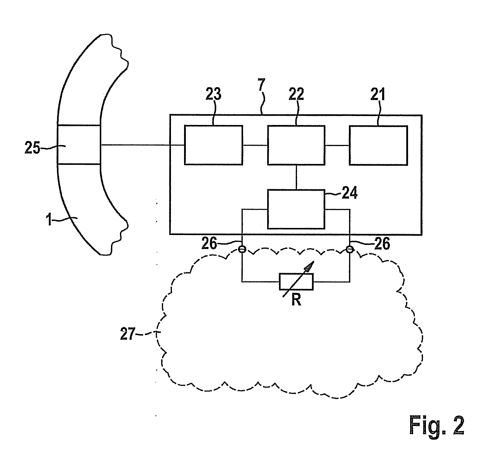
[0011]In one particularly preferred specific embodiment of the movement sensor according to the present invention, it is provided that an additional sensor for detecting the changing environmental conditions is assigned to the movement sensor. In particular, water may be differentiated from air by the additional sensor. For example, a sensor for detecting the moisture, the temperature, the pressure, and / or the resistance is particularly preferably provided as the additional sensor. For example, a capacitive moisture sensor may be used to detect the moisture. If this sensor detects moisture of a specific or predefinable degree, it may be concluded that the sensor and therefore the person is located in water. Another option is a temperature sensor as an additional sensor. The water temperature typically differs from the air temperature, so that upon the detection of a sudden temperature change, it may be concluded that the person has changed from the air into the water. Typical water temperatures, as are to be encountered in the swimming pool, for example, may be taken into consideration for this purpose, so that incorrect interpretations do not occur when the person changes from an interior to the outside, for example. Here also, a sudden temperature change may occur. Furthermore, a pressure sensor may be used as an additional sensor, for example, since different pressure conditions prevail in the water than outside the water. Another option is the measurement of the resistance, in particular the transition resistance between two contacts, for example, between the contacts of a charging plug. The resistance between two contacts depends on the ambient medium, and therefore the transition resistance changes between two contacts when a change takes place between water and air. By monitoring the resistance, it may therefore be detected whether the movement sensor is in the water or in the air. The use of the resistance measurement between two contacts has the particular advantage that such contacts are typically present in any case, in particular if the movement sensor is operated via batteries, so that no further components are necessary for the additional sensor for detecting air or water. If the movement sensor is operated via batteries, contacts are typically led outward in order to charge the battery. These contacts are generally monitored in that it is checked whether a charging current is present, for example. In this way it may be detected whether the movement sensor is in a charging station. Only a slight modification of the sensor, e.g., an additional terminal on an A / D converter, is necessary to monitor the transition resistance between these contacts with respect to a detection of the environmental conditions. The following states may thus be detected on the basis of these contacts:
[0012]sensor in the charging station (e.g., charging current present and additionally a “short-circuit” of the contacts through the voltage source)
[0013]sensor in the air (high internal resistance between the contacts)
[0014]sensor in the water (low internal resistance between the contacts).
[0015]In this specific embodiment, it is possible without special effort, in addition to establishing the movement profile through the movement sensor, to establish whether the movement sensor is located in the water or in the air, so that the corresponding operating mode may be set automatically without user intervention.

Problems solved by technology

However, a changeover or a change of the operating mode is primarily problematic in the field of medicine and primarily represents an impediment in the case of older patients or patients who are restricted in any way.
This may be because the particular patient is possibly not technically adept.
The operation of a button or the operating selection via a menu may be difficult in the case of small buttons or a small display screen, in particular if the patient is restricted with respect to motor skills or vision.
Above all, a changeover of the operating mode requires a certain attentiveness and concentration, which may not always be expected in particular in the case of longer-term establishment of a movement profile over multiple hours or over an entire day, so that deficient operation of corresponding sensors and therefore incorrect interpretation and classification of the sensor signals easily occur.
Of course, such incorrectly established movement profiles are not very meaningful.
Here also, a sudden temperature change may occur.
A separate power supply on the fastening element requires additional contacts for the power supply, which increase the complexity and therefore possibly make it more difficult to handle.

Method used


Image

  • Movement sensor and system for establishing a movement profile
  • Movement sensor and system for establishing a movement profile
  • Movement sensor and system for establishing a movement profile

Examples


Embodiment Construction

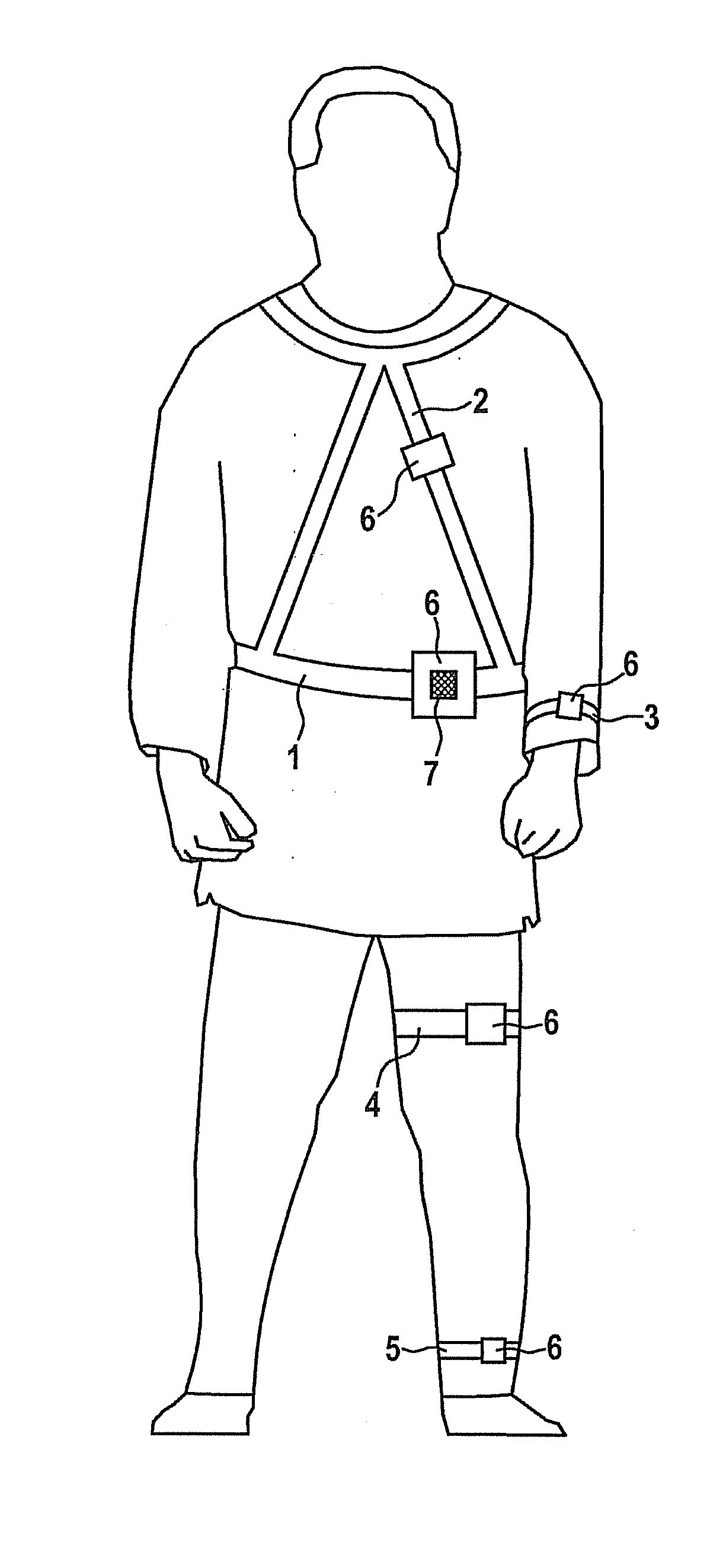
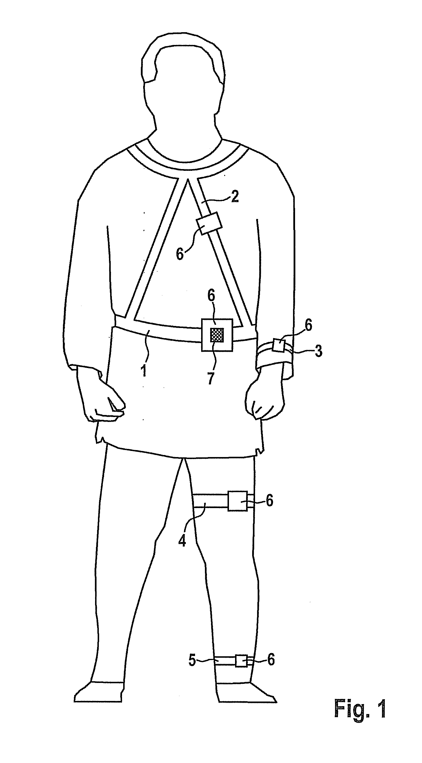
[0033]The person shown in FIG. 1 carries multiple fastening elements in the form of a hip strap 1, a chest strap 2, a wristband 3, a thigh strap 4, and a lower leg or foot strap 5. These fastening elements each have a device 6 for fastening a movement sensor. These may be clips, snap fasteners, guide rails, pockets, or comparable elements, for example. Devices 6 of fastening straps 1, 2, 3, 4, and 5 are equipped with an identifier, which may be electronically analyzed by movement sensor 7. In this example, movement sensor 7 is fastened on fastening device 6 of hip strap 1. Through the individual identifier of the fastening device on hip strap 1, movement sensor 7 may electronically read out this identifier and therefore infer its position on the body of the person, in this case the position in the middle of the body or on the hip of the person. Since the various body parts are subject to different movement patterns during various physical activities of the person, the signals detect...


PUM


Abstract

A movement sensor for establishing a movement profile of a living being, in particular a human, is characterized in that the movement sensor has an arrangement for automatically changing between various operating modes.

Description

FIELD OF THE INVENTION[0001]The present invention relates to a movement sensor and a system for establishing a movement profile of a living being, in particular a human, and the use of a movement sensor for establishing a movement profile.BACKGROUND INFORMATION[0002]Devices for detecting movements or physical activity have been available for some time from the field of sports. For example, watches are used, which allow the pulse to be monitored. A movement sensor in a shoe allows detection of the cadence during cycling. Comparable sensors are also available in the field of medicine, with the aid of which a movement or activity profile of the patient may be established. Such movement profiles may be helpful within the scope of a diagnosis or therapy, e.g., in the case of overweight patients or during rehabilitation measures.[0003]It is often necessary to establish a movement profile of the patient over a long period of time, for example, over 24 hours or more, in order to be able to ...

Claims


Application Information

Patent Timeline
IPC IPC(8): G01P15/00G01C9/00
CPCA61B5/1118A61B5/1123A61B5/68A61B5/681A61B2562/0219A61B5/6829A61B5/6831A61B2505/09A61B2560/0223A61B5/6828
Inventor KLOSE, HANS-PETERSOHNKE, THORSTENWITTIG, THOMAS
Owner ROBERT BOSCH GMBH
Learn More