
Control method for converting power, and electronic power converter adapted to carry out said method

Active Publication Date: 2012-05-10
INGETEAM POWER TECH
View PDF5 Cites 22 Cited by
  • Summary
  • Abstract
  • Description
  • Claims
  • Application Information

AI Technical Summary

Benefits of technology

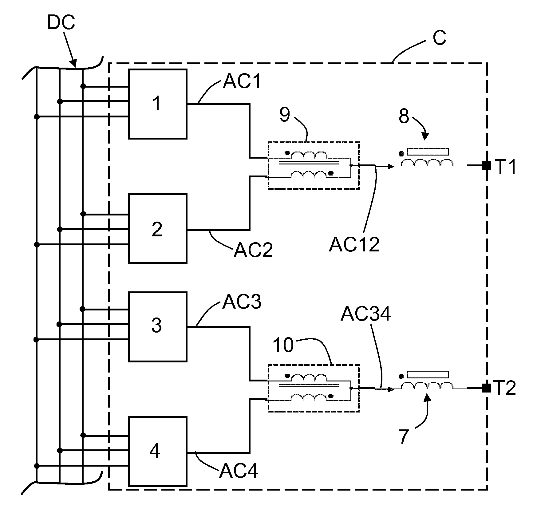
[0011]It is an aspect of the invention to provide a method for converting a DC voltage into an alternating voltage for transmission and / or distribution lines, and a converter adapted to carry out said method, in order that the power supplied to the transmission and / or distribution lines comprises a high voltage value while also presenting optimal waveform quality.
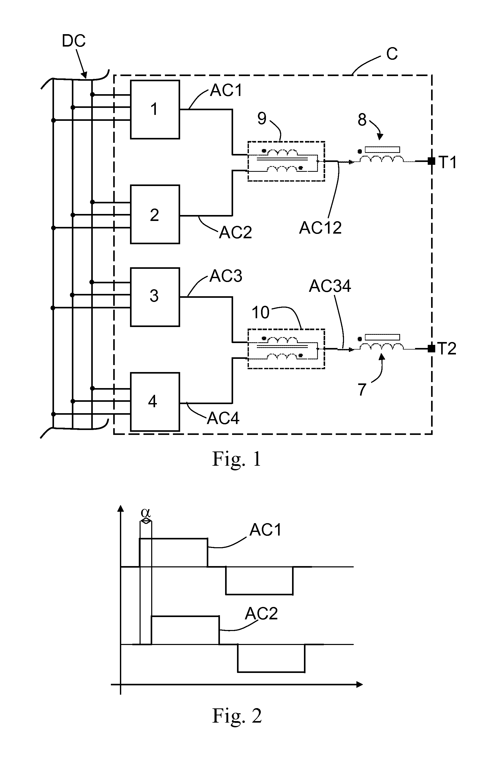
[0014]The additional resulting alternating voltage waveform is phase-shifted by approximately 180° in relation to the resulting alternating voltage waveform, so that thanks to the control method of the invention two voltage signals are generated and which are adapted to correspond with two output signals of the converter (voltage waves in two terminals of said converter), said terminals being used to couple the converter to a load (preferably the load corresponds with a transmission and / or distribution line). As a result, as the voltage waves of the two terminals that are used to couple the converter to a load are substantially in opposition, the voltage of the output voltage waveform of said converter is also practically doubled, thereby providing a high-power converter in a simple and economic manner, without the need for additional elements that would make said converter more expensive.
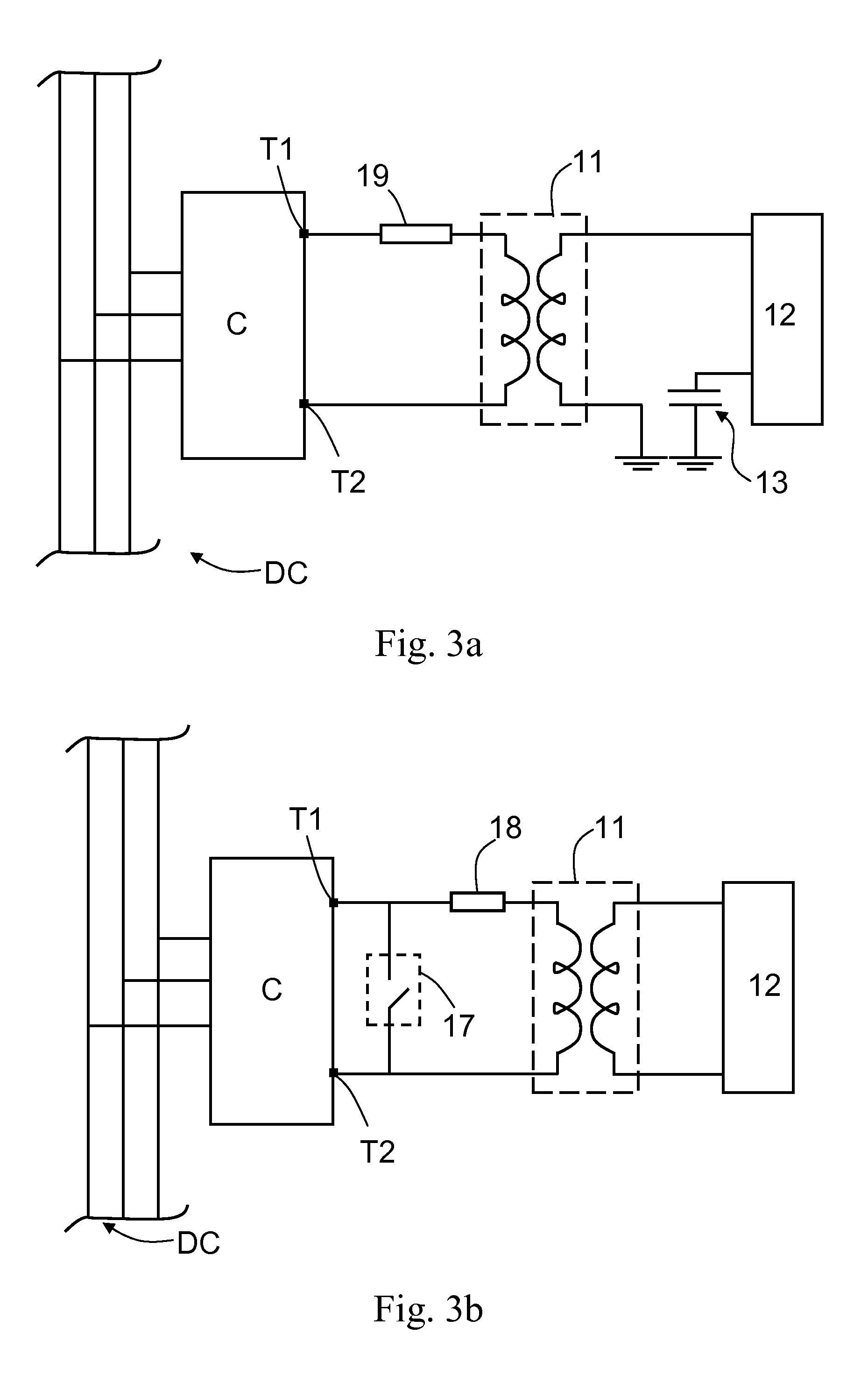
[0015]As a result of this control method, two voltage waves are obtained and are adapted to be supplied through two terminals of the converter, enabling a converter with two open poles on the output to be coupled to a load (preferably the load corresponds with a transmission and / or distribution line), generally by means of a specific magnetic component. Thanks to the arrangement of converter used by the control method, said magnetic component can comprise a coupling transformer with a single coil on the secondary, where the two terminals of the converter are connected, so that an electronic power converter with less magnetic components than those previously necessary is obtained. This results in a more economical converter, and also a reduction in the associated high-voltage switchgear which was previously necessary and which would involve a very high cost. This implies a reduction in the size of the magnetic components that are used, which results in a smaller size of the converter, which can be advantageous in some situations.
[0016]According to these aspects, the common-mode voltages may also be eliminated in an ordinary manner from at least one of the alternating voltage waves, as a result of which the quality of the voltage waveform applied in the load is optimal, the low number of inverters being used, which implies a reduction in the cost and the size of the resulting converter in relation to those used in the prior art. This also allows the use of modulation techniques that produce a zero-sequence voltage component, for the purposes of increasing the voltage of the output voltage waveform and the power supplied by the converter, in a simple manner.

Problems solved by technology

The greater the number of levels, the greater the complexity in implementing the converter (of the inverters), as a result of which, and generally speaking, industrial applications are usually based on inverters or branches of up to two or three levels at most.

Method used


Image

  • Control method for converting power, and electronic power converter adapted to carry out said method
  • Control method for converting power, and electronic power converter adapted to carry out said method
  • Control method for converting power, and electronic power converter adapted to carry out said method

Examples


first embodiment

[0030]To reduce the harmonic content of the output voltage to be supplied to the load 12, PWM modulation (Pulse Width Modulation) type techniques are used, in which the shape of the output waveform is obtained by comparing an modulated output waveform (for instance at a frequency of 50 Hz) with a high-frequency triangular waveform (for instance 600-10,000 Hz) to obtain an output voltage waveform of low harmonic content. This PWM modulation may be carried out by using the respective modulating waves M1 and M2 displaced in phase in relation to each other in both inverters 1 and 2; 3 and 4 whose alternating output voltage waves AC1 and AC2; AC3 and AC4 are combined in parallel, and the triangular waves 21 and 22 that are equal and in phase, as shown in FIG. 5, or with the modulating waves M1 and M2 in phase and the triangular waves 21 and 22 equal but displaced in phase in relation to each other, preferably by approximately 90°. A combination of the two can also be adopted, in other w...

second embodiment

[0031]To reduce the harmonic content of the output voltage, selective harmonic elimination or SHE modulation techniques are used, and by means of which the phase displacements of the switching signals to the semiconductors of the different inverters 1, 2, 3 and 4 are controlled, the two fundamental waves of the different inverters 1 and 2; 3 and 4 whose alternating output voltage waves AC 1 and AC2; AC3 and AC4 are combined in parallel being in phase or otherwise. As a result, certain harmonics of the alternating voltage waves AC1, AC2, AC3 and AC4 are eliminated or reduced, which results in a reduction of the harmonic content of said alternating voltage waves AC1, AC2, AC3 and AC4.


PUM


Abstract

A control method and apparatus are provided to convert a DC voltage into alternating voltage. The apparatus includes a first inverter and a second inverter to generate a first alternating voltage and a second alternating voltage, respectively. Also included is an interphase transformer to combine these alternating voltages in parallel to obtain a first resulting alternating voltage. The apparatus also includes a third inverter and a fourth inverter to generate a third and fourth alternating voltage, respectively. These are combined to form a second resulting alternating voltage. The second resulting alternating voltage is displaced in phase approximately 180° in relation to the first resulting alternating voltage.

Description

INCORPORATION BY REFERENCE[0001]This application claims priority from Spanish Patent Application No. P201031637 filed on Nov. 8, 2010 including the specification, drawings and abstract thereof, the disclosure of which is incorporated herein by reference in its entirety.TECHNICAL FIELD[0002]Aspects of the invention relate to control methods in high-power environments, and in particular to control methods for converting energy for transmission and / or distribution lines from a DC voltage. Aspects of the invention also relate to electronic power converters adapted to carry out said control methods.BACKGROUND OF THE INVENTION[0003]Electronic power converters are currently used in a wide range of applications where a DC / AC conversion is required, carried out by means of inverters comprised by said converters, such as variable-speed drives, variable-speed wind turbines, solar inverters, UPS (Uninterruptible Power Supplies) systems or FACTS (Flexible AC Transmission Systems) devices.[0004]I...

Claims


Application Information

Patent Timeline
IPC IPC(8): H02M7/44H02M1/00H02M7/487H02M7/49
CPCH02M7/49H02M7/487H02M2001/009H02M1/009
Inventor CHIVITE ZABALZA, FRANCISCO JAVIERRODRIGUEZ VIDAL, MIGUEL ANGELMADARIAGA ZUBIMENDI, DANELIZURZA MORENO, PEDROCALVO OLALLA, GORKA
Owner INGETEAM POWER TECH
Learn More