
Free form lighting module

a technology of free form lighting and modules, applied in the direction of fixed installations, lighting and heating apparatus, instruments, etc., can solve the problem that prior art systems may not have the ability to provide light to both sides of a flat waveguid

Active Publication Date: 2012-05-10
SIGNIFY HLDG BV
View PDF38 Cites 72 Cited by
  • Summary
  • Abstract
  • Description
  • Claims
  • Application Information

AI Technical Summary

Benefits of technology

[0006]Prior art systems may not have the ability of providing light to both sides of a flat waveguide. There is however a desire to provide a lighting device that is able to provide light to two directions: for instance uplight directed to a ceiling to provide indirect illumination that can be used as atmosphere / mood lighting and downlight for target (task) lighting. Uplight may contribute to a more convenient lighting of a space, such as a room or an office, and may contribute to the fulfillment of the UGR (unified glare rating) norm for offices. Such a device may be used in homes, offices, hospitality areas, etc. There is further a desire to provide such a device, wherein the relative amounts of uplight and downlight are tunable.
[0015]Incoupled light, i.e. light within the waveguide, impinging on the first face might, dependent on the structures, escape from the waveguide. In order to minimize loss of light escaping from parts of the waveguide other than the cavity and the second face, a reflector may be arranged downstream of the first face comprising structures. Hence, in a specific embodiment, the illumination device further comprises a reflector, arranged to reflect light escaping from the first face back into the waveguide. Further, such reflector may also be used as, or be in contact with, a heat sink, arranged to facilitate removal of heat from the waveguide. In a specific embodiment, the first face is in contact with a heat sink; i.e. at least part, preferably a substantial part, of the first face comprising structures is in contact with a heat sink.
[0021]In a specific embodiment, the illumination device further comprises a diffuser, arranged downstream of the second face. Such a diffuser may facilitate the mixing of different light rays escaping from the second face. Especially, when a plurality of different emission colors is used, such a diffuser may be beneficial. Typical diffusers are for instance translucent materials. The diffuser may for instance be a holographic diffuser. Also various diffuser foils can be used, such as light-shaping diffusers from Luminit (“holographic diffusers”), diffusers from Fusion Optix or Bright View Technologies).
[0026]Glare-suppression optics is especially arranged to pass substantially all light escaping from the second face and the optional diffuser in such a way that glare may be reduced.
[0034]In yet a further embodiment, the illumination device may further comprise a spacing downstream of the second face and upstream of one or more of the diffuser and glare-suppression optics. The optional diffuser and the optional glare-suppression optics or another exit window, may be arranged at a distance from the second face. Preferably, one or more of the diffuser and glare-suppression optics are present, and one or more of these are arranged at a non-zero distance from the second face, respectively. In this way, a kind of spacing is provided. Especially, when a plurality of different emission colors is used, such spacing may be beneficial. The spacing may contain a vacuum or a gas, such as air. Especially, the optics downstream of the waveguide face(s) are not in optical contact with the waveguide face(s) or each other. Non-optical contact may be obtained by arranging the optics at distances such as at least about 5 μm, like at least about 10 μm, such as in the range of 5-500 μm, like 10-250 μm.

Problems solved by technology

Prior art systems may not have the ability of providing light to both sides of a flat waveguide.

Method used


Image

  • Free form lighting module
  • Free form lighting module
  • Free form lighting module

Examples


Embodiment Construction

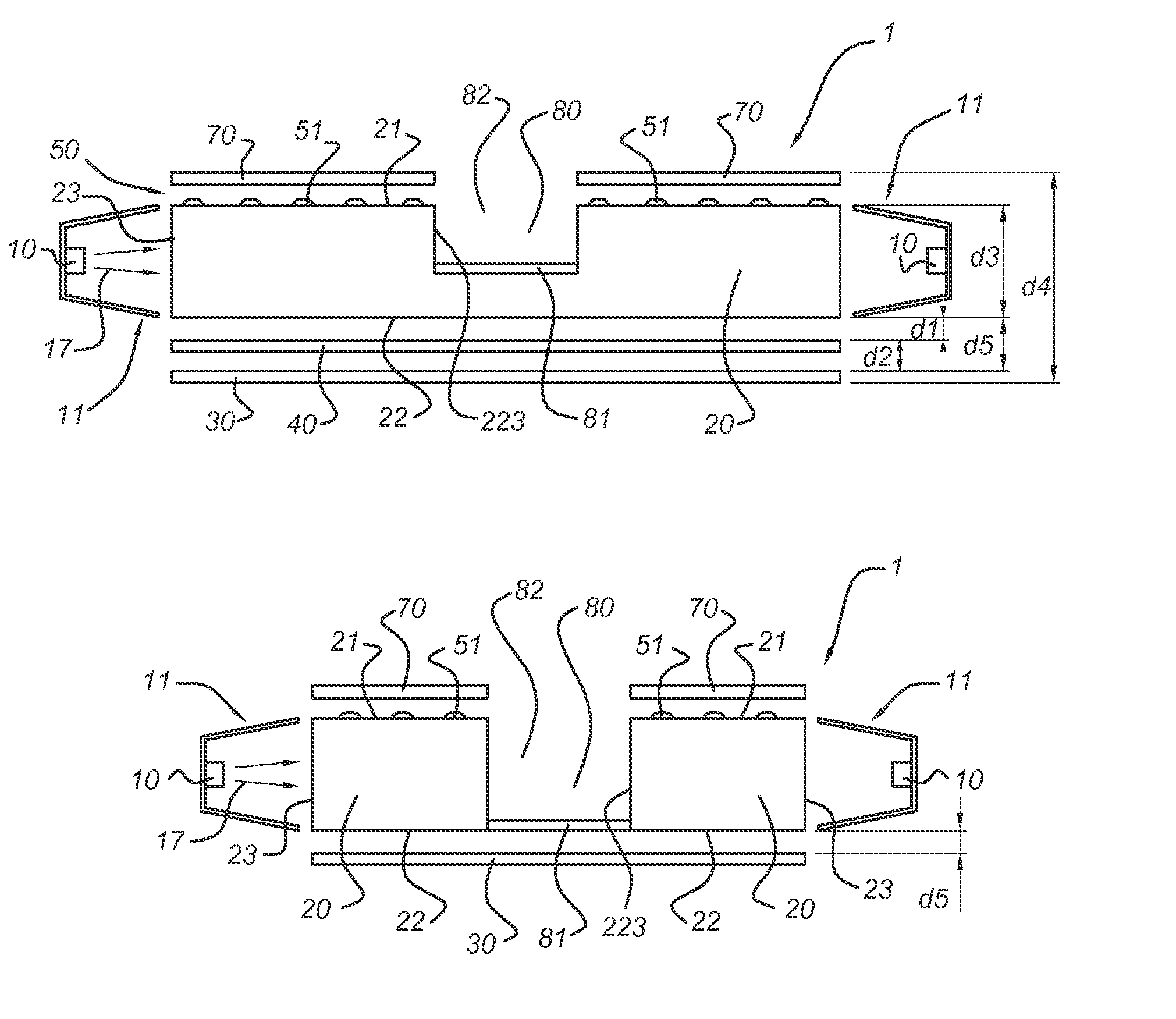
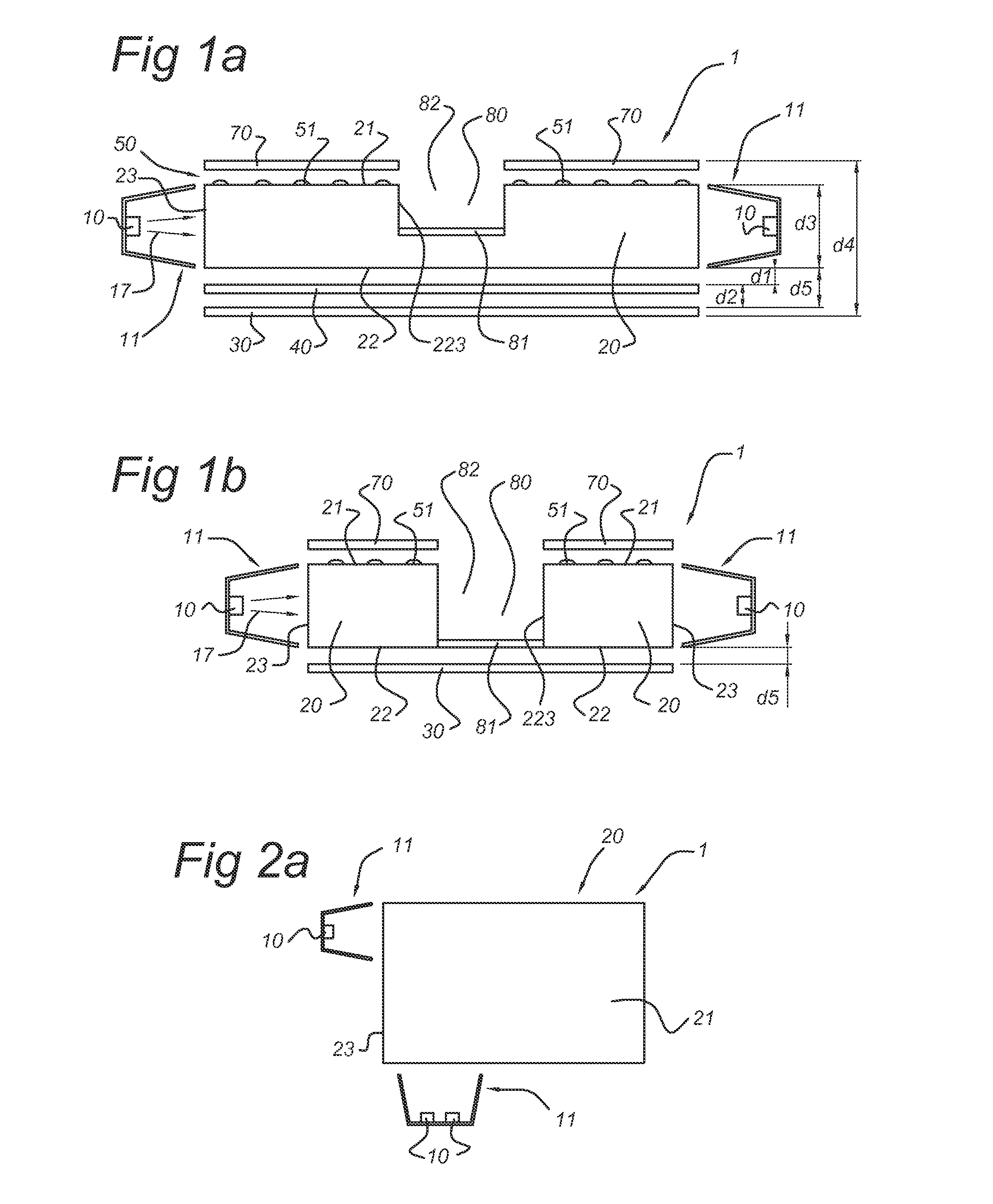
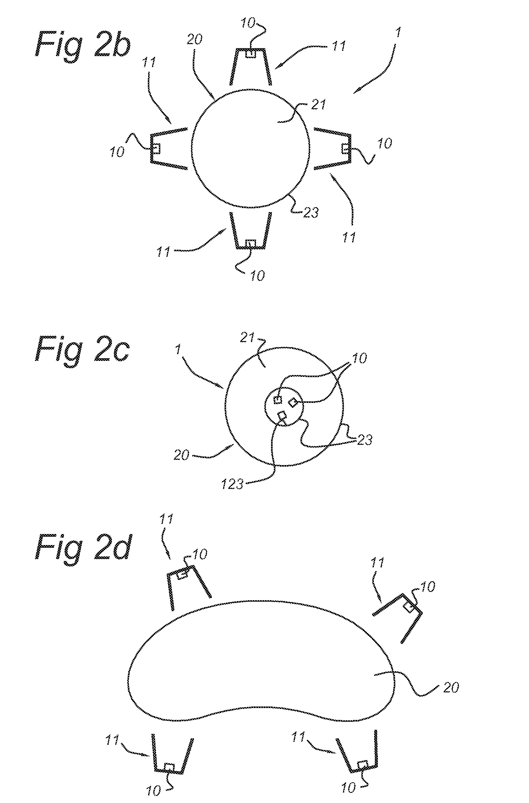
[0049]FIG. 1a schematically depicts an illumination device 1 according to an embodiment of the invention. The illumination device 1 comprises a waveguide element 20. This waveguide element 20 comprises a first face 21, which is also indicated as top face, and a second face, indicated with reference 22, which is also indicated as bottom face. The edge is indicated with reference 23. The waveguide 20 may be made of any material known in the art, such as transplant plastics, glass, etc. At the edge of the waveguide, a light source 10, especially a LED, is arranged, which is arranged to provide light 17, also indicated as LED light 17, for incoupling into the waveguide 20 via edge 23. Optionally, collimator optics 11 may be present, arranged to collimate, at least part of the LED light 17, into the edge 23 of the waveguide 20. The light that enters the waveguide 20 via edge 23 will travel through the waveguide 20 and may reach top face 21.

[0050]Top face 21 comprises structures 51, which...


PUM


Abstract

The invention provides an illumination device (1) comprising (a) a waveguide element (20) comprising a first face (21), a second face (22), and a waveguide edge (23), and (b) a LED light source (10), arranged to generate light source light (17), with optional collimating optics (11). The LED light source (10) with optional collimating optics (11) is arranged to couple at least part of the light source light (17) into the waveguide element (20) via the waveguide edge (23) of the waveguide element (20). The first face (21) comprises structures (51) arranged to couple at least part of the light out of the waveguide element (20) via the second face (22) to provide second face light (37). The illumination device (1) further comprises a cavity (80), arranged to allow light to escape from the waveguide element (20) into the cavity (80), and a reflector (81), arranged to reflect at least part of the light in the cavity (80) in a direction away from the second face (22) to provide first face light (47). Such an illumination device may allow lighting a room, for instance via the ceiling with uplight, and lighting a specific area in the room with downlight. Further, a relatively thin illumination device may be provided, which may for instance suspend from a ceiling.

Description

FIELD OF THE INVENTION[0001]The invention relates to an illumination device comprising a waveguide.BACKGROUND OF THE INVENTION[0002]Waveguide systems in lighting, especially in LCD backlighting, are known in the art.[0003]GB 2430071 for instance has for its object to provide a backlight unit having good display quality, and a liquid crystal display device provided with the same. To this end, a light source, a reflection sheet, a light guide plate, a gas space, and a diffusion plate are installed. The reflection sheet, light guide plate, gas space, and a diffusion plate are superposed in the order mentioned. The light source is in the form of individual light sources having different spectra or different amounts of luminescence and being disposed in the vicinity of the incident surface of the light guide plate. The surface of the light guide plate opposite to the reflecting sheet is provided with scattering dots, whereby the light transmitted through the light guide plate is taken ou...

Claims


Application Information

Patent Timeline
IPC IPC(8): F21V7/04
CPCG02B6/0036G02B6/0043G02B6/0045G02B6/0063G02B6/0068G02B6/0073G02F2001/133628G02F1/133615F21S8/06F21V14/04F21V14/08F21Y2101/02G02B6/0078F21Y2115/10G02F1/133628
Inventor VAN DIJK, ERIK MARTINUS HUBERTUS PETRUSBOONEKAMP, ERIKVAN DER WAL, RENE HENRI WOUTERDINGEMANS, ANTONIUS PETRU MARINUS
Owner SIGNIFY HLDG BV
Learn More