
Storage apparatus and data control method

a technology which is applied in the field of storage apparatus and data control method, can solve the problems of data not being able to be erased, data cannot be no longer erased, and unusable, and achieve the effect of improving data capacity efficiency

Active Publication Date: 2012-04-26
HITACHI LTD
View PDF2 Cites 41 Cited by
  • Summary
  • Abstract
  • Description
  • Claims
  • Application Information

AI Technical Summary

Benefits of technology

[0012]According to the present invention, it is possible to improve the data capacity efficiency by de-duplicating data assigned with a guarantee code that is different for each data.

Problems solved by technology

Nevertheless, since the erase time of a flash memory is longer than its write time, generally speaking, a method is adopted where, upon writing data, old data is once read and thereafter combined with the write data to create update data, the created update data is written into a separate unwritten area, and invalidating the original recording area (processing which disables the referral from a host system).
Nevertheless, with a flash memory, there is a limit in the number of times that the data can be erased.
Thus, with a data area in which the rewriting of data is concentrated and erase count has increase, data can no longer be erased and it will become unusable.
Moreover, with a flash memory, since a page that is once written will also entail an increased read error rate with the lapse of time, an operation referred to as “refresh” of writing a page in which a given period of time has elapsed from the writing thereof to a separate page is required.

Method used


Image

  • Storage apparatus and data control method
  • Storage apparatus and data control method
  • Storage apparatus and data control method

Examples


first embodiment

(1) First Embodiment

[0037](1-1) Hardware Configuration of Computer System

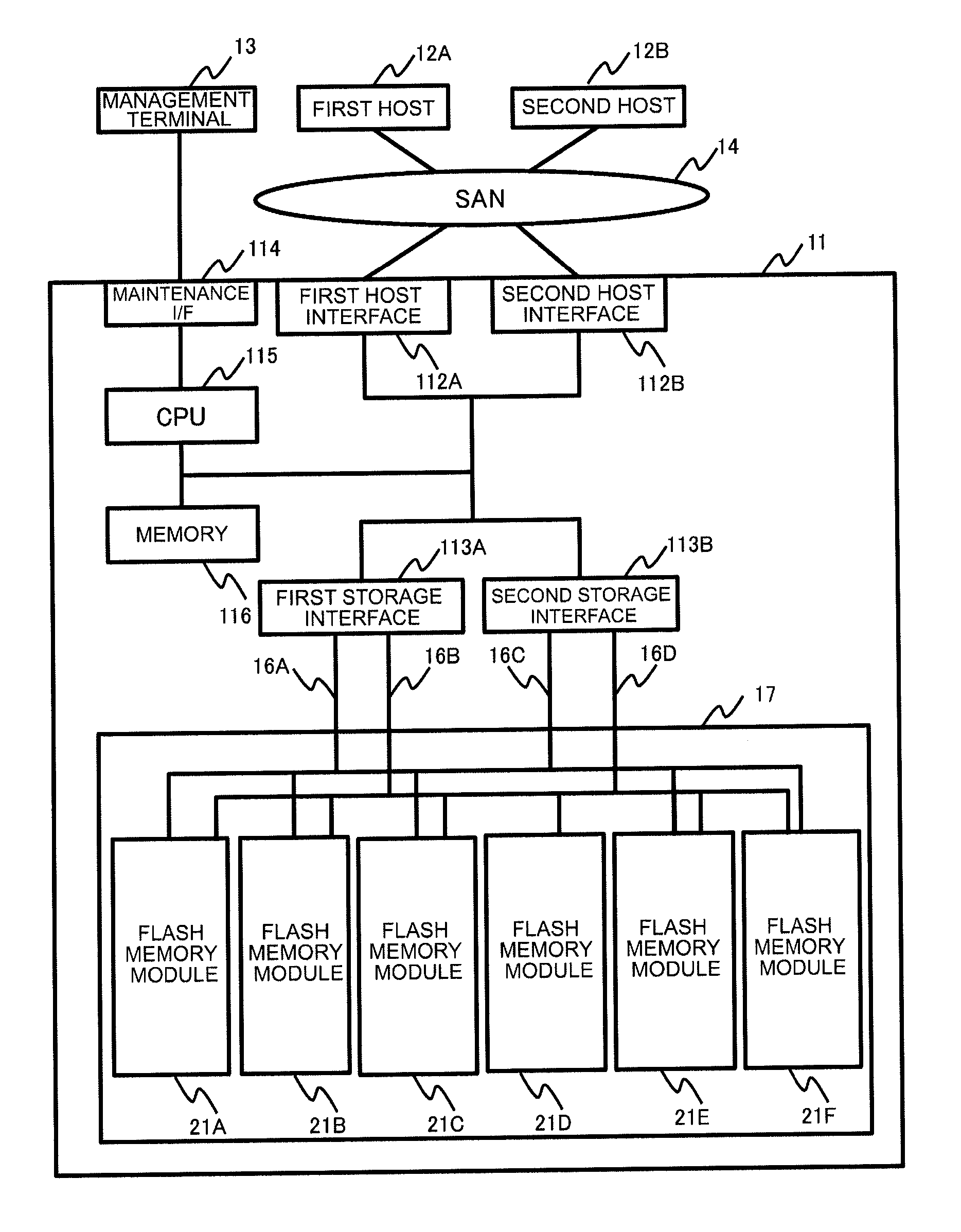
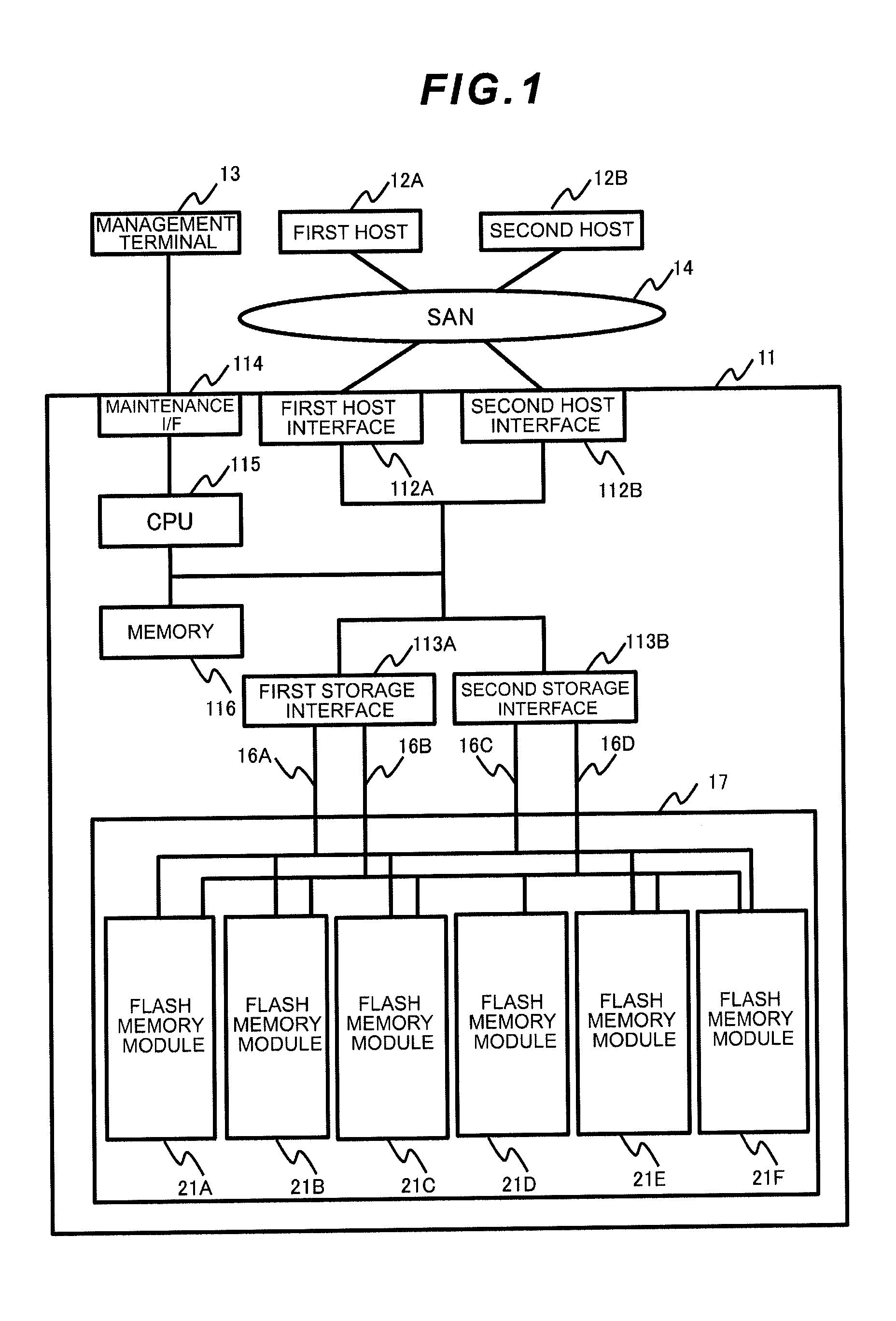
[0038]The hardware configuration of the computer system 1 according to this embodiment is foremost explained. As shown in FIG. 1, the computer system 1 according to this embodiment comprises a storage apparatus 11, first and second hosts 12A, 12B (the first and second hosts are hereinafter sometimes simply referred to as the “host 12”), a management terminal 13, and a SAN (Storage Area Network) 14.

[0039]The storage apparatus 11 interprets commands sent from the host 12, and executes reading / writing of data into a storage area of the storage apparatus 11. The storage apparatus 11 is configured, as shown in FIG. 1, from first and second host interfaces 112A, 112B (the first and second host interfaces are hereinafter sometimes simply referred to as the “host interface 112”), first and second storage interfaces 113A, 113B (the first and second storage interfaces are hereinafter sometimes simply referred to as the “...

second embodiment

(2) Second Embodiment

[0135](2-1) Hardware Configuration of Computer System

[0136]Since the hardware configuration of the computer system 2 according to this embodiment is the same as the hardware configuration of the computer system 1 according to the first embodiment, the detailed explanation thereof is omitted. This embodiment is common with the first embodiment in that the de-duplication of a plurality of logical pages is performed, but differs from the first embodiment in that the data part to be de-duplicated is additionally compressed. Note that, in this embodiment also, as a method of searching for the logical page to be de-duplicated, for example, the combination of logical pages to be de-duplicated is searched among large-size data upon writing large-size data or during data reallocation in the reclamation processing or the refresh processing. Moreover, it is also possible to calculate and manage the hash value of the data part of the respective pages, and dynamically search...

third embodiment

(3) Third Embodiment

[0174](3-1) Hardware Configuration of Computer System

[0175]The hardware configuration of the computer system 3 according to this embodiment differs in that the flash memory storage 17 of the computer system 1 according to the first embodiment is configured as a device that is separate from the storage apparatus 11. This embodiment is common with the first embodiment in that a plurality of logical pages are subject to de-duplication, but differs in that the storage apparatus 11 and the flash memory storage 17 jointly execute the de-duplication. Specifically, the data traffic is reduced by the storage apparatus 11 sending a specific pattern rather than sending actual data to the flash memory storage 17 regarding the format data and the like to be written into a storage area according to a request from the host 12.

[0176](3-2) Detailed Operation of Computer System

[0177]The de-duplication processing that is executed between the storage apparatus 11 and the flash memor...


PUM


Abstract

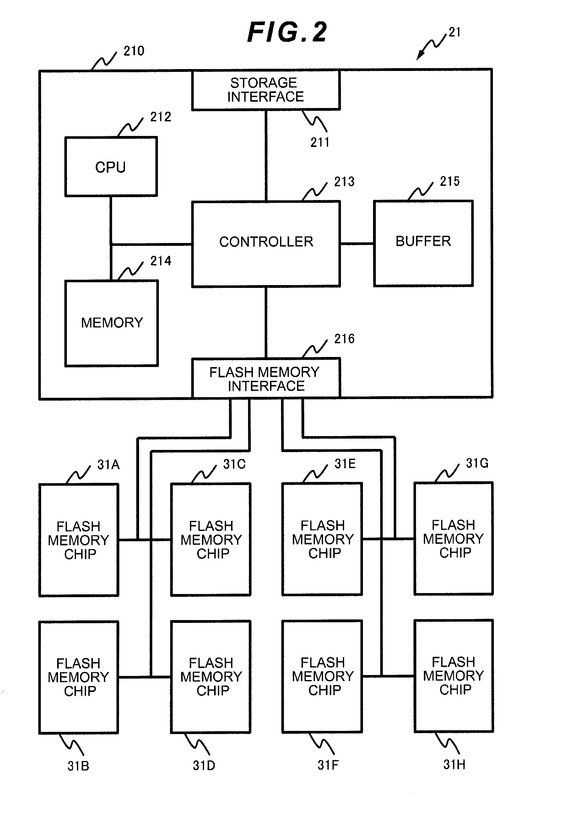
Data capacity efficiency is improved by de-duplicating data assigned with a code that is different for each data.A storage apparatus comprising a flash memory control device equipped with one or more flash memory modules, wherein the flash memory module comprises at least one flash memory chip for providing a storage area, and a controller for controlling writing / reading of data including user data and a guarantee code accompanying the user data to and from the storage area provided by the flash memory chip, wherein the controller respectively divides a plurality of the data having the common user data into the user data and the guarantee code, stores one of the user data in an area of a predetermined unit of the storage area, and links and stores each of the guarantee codes accompanying the plurality of user data in an area of a predetermined unit of the storage area.

Description

TECHNICAL FIELD[0001]The present invention relates to a storage apparatus and a data control method, and in particular can be suitably applied to a storage apparatus and a data control method that uses a device, in which rewriting is limited, as the storage medium.BACKGROUND ART[0002]Conventionally, in a storage apparatus, a non-volatile storage medium capable of random access; for example, a magnetic disk or an optical disk, has been used as the data storage medium. Particularly in recent years, a storage apparatus comprising numerous compact disk drives is becoming mainstream.[0003]Moreover, pursuant to the advancement of semiconductor technology in recent years, a non-volatile semiconductor memory capable of bulk erasing has been developed. As an example of this type of non-volatile semiconductor memory, there is a flash memory. A storage apparatus that uses a flash memory as its storage medium is considered to be superior in terms of power saving and faster access time in compar...

Claims


Application Information

Patent Timeline
IPC IPC(8): G06F12/00
CPCG06F3/0608G06F3/0616G06F3/0641G06F3/0688G11C16/0483G06F11/108G11C16/04G06F2212/7202G06F12/0246G06F11/1044G06F3/0679
Inventor KAWAMURA, ATSUSHIOGAWA, JUNJI
Owner HITACHI LTD
Learn More