Heating exchange chamber for liquid state cooling fluid
- Summary
- Abstract
- Description
- Claims
- Application Information
AI Technical Summary
Benefits of technology
Problems solved by technology
Method used
Image
Examples
first embodiment
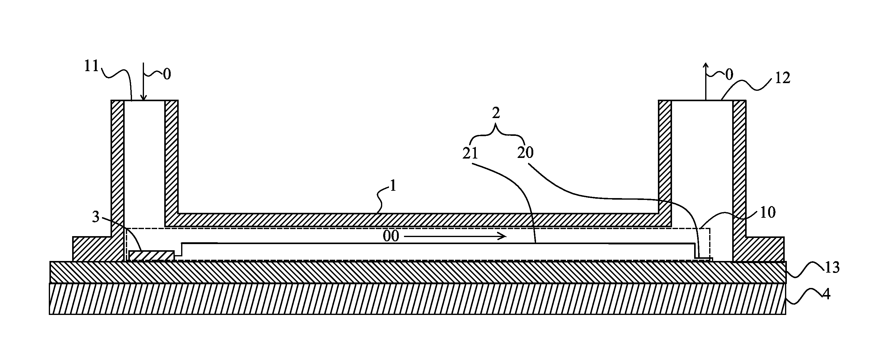
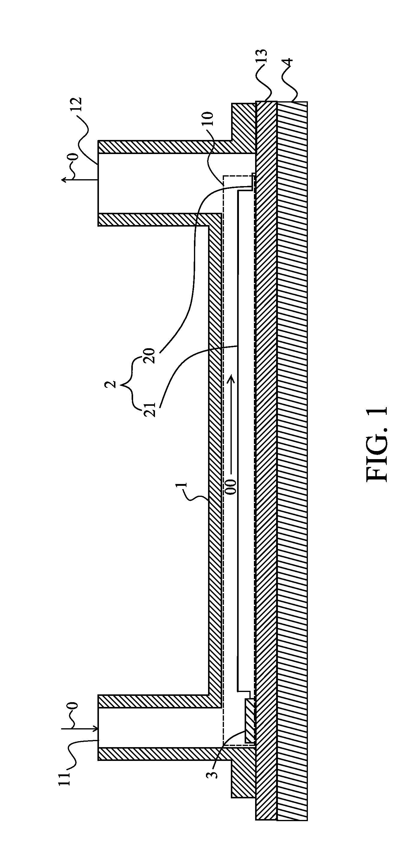
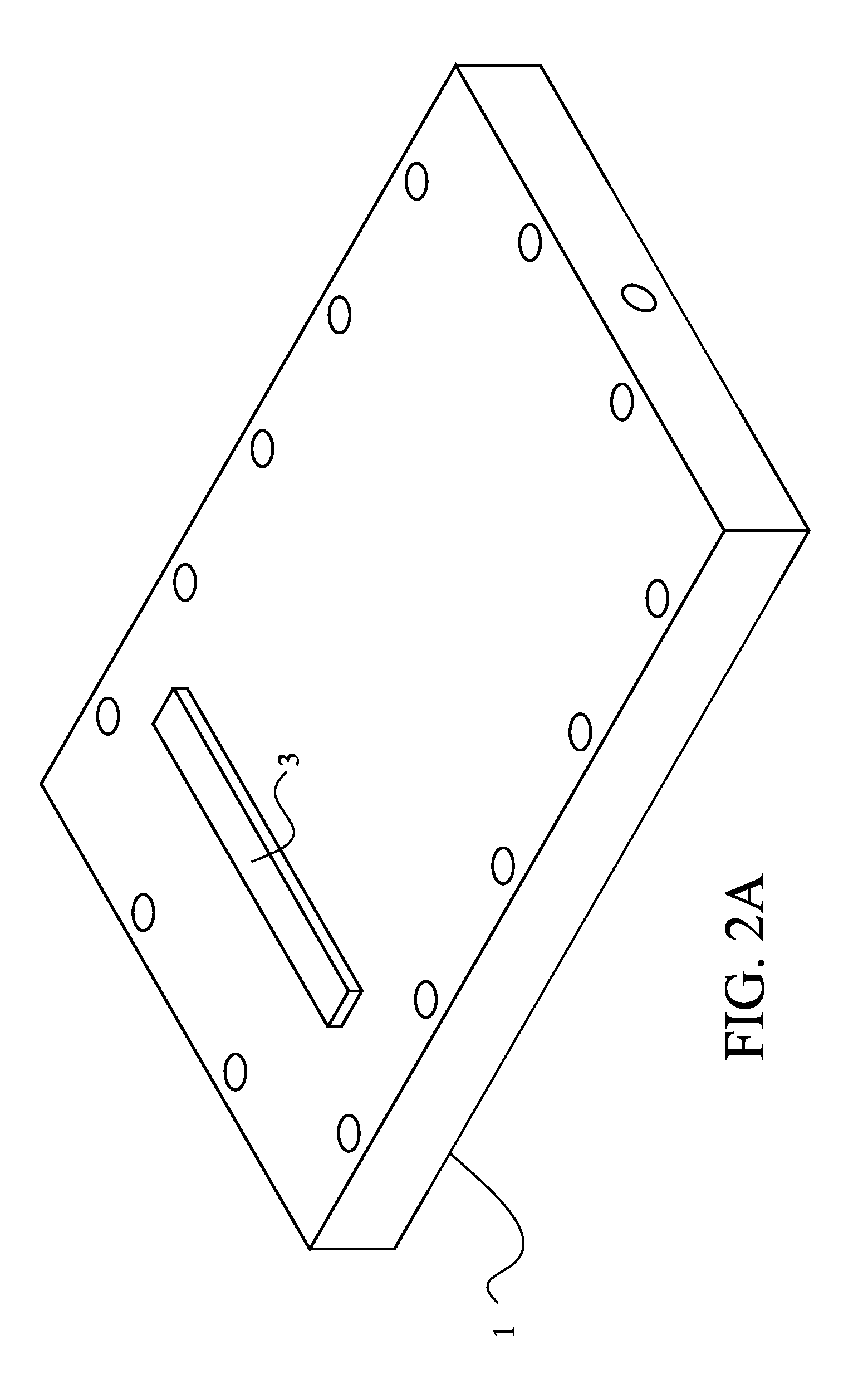
[0015]Please refer to FIG. 1 and FIG. 2A, which is a schematic diagram showing a heat exchange chamber for liquid state cooling fluid according to the present invention, and a schematic diagram showing a flow resistance according to the invention. As shown in FIG. 1, the heat exchange chamber comprises: a casing 1, a thermal dissipation device 2, and a flow resistance 3. The casing 1 is configured with a cavity 10, an inlet 11 and an outlet 12 in a manner that the inlet 11 is provided for allowing a cooling fluid 0 to flow into the cavity 10 and the outlet 12 is provided for allowing the cooling fluid 0 to flow out of the cavity 10 as the cooling fluid is enabled to flow in a flowing direction through the cavity 10, as the arrow 00 shown in FIG. 1. In this embodiment, the diameter of the outlet 12 is larger than that of the inlet 11, by that the cavity 10 can be prevented from having too much gas being accumulated therein, and thus the boiling point of the cooling fluid 0 can be pre...
second embodiment
[0016]Please refer to FIG. 2B and FIG. 2C, which is a schematic diagram showing a flow resistance according to the invention, and a partial top view of FIG. 2B. As shown in FIG. 2B, the flow resistance 3, that is composed of a plurality of protrusions 30, is designed for narrowing down a flow channel from the inlet 11 to the cavity 10 so as to raise the resistance to the flow of the cooling fluid 0 before the cooling fluid flows through a thermal dissipation device 2, and thus enable the cooling fluid 0 to be distributed uniformly through the thermal dissipation device 2. As shown in FIG. 2C, the two sides of each protrusion is formed with a first ramp 300 and a second ramp 301, and consequently, by the defining of two corresponding first ramps 300 on any two neighboring protrusions 30, a converging channel 302 is formed, and the same time, by the defining of two corresponding second ramps 301 on any two neighboring protrusions 30, a diverging channel 303 is formed. With the formati...
PUM
 Abstract
Description
Claims
Application Information
 - R&D
- Intellectual Property
- Life Sciences
- Materials
- Tech Scout
- Unparalleled Data Quality
- Higher Quality Content
- 60% Fewer Hallucinations
Browse by: Latest US Patents, China's latest patents, Technical Efficacy Thesaurus, Application Domain, Technology Topic, Popular Technical Reports.
© 2025 PatSnap. All rights reserved.Legal|Privacy policy|Modern Slavery Act Transparency Statement|Sitemap|About US| Contact US: help@patsnap.com


