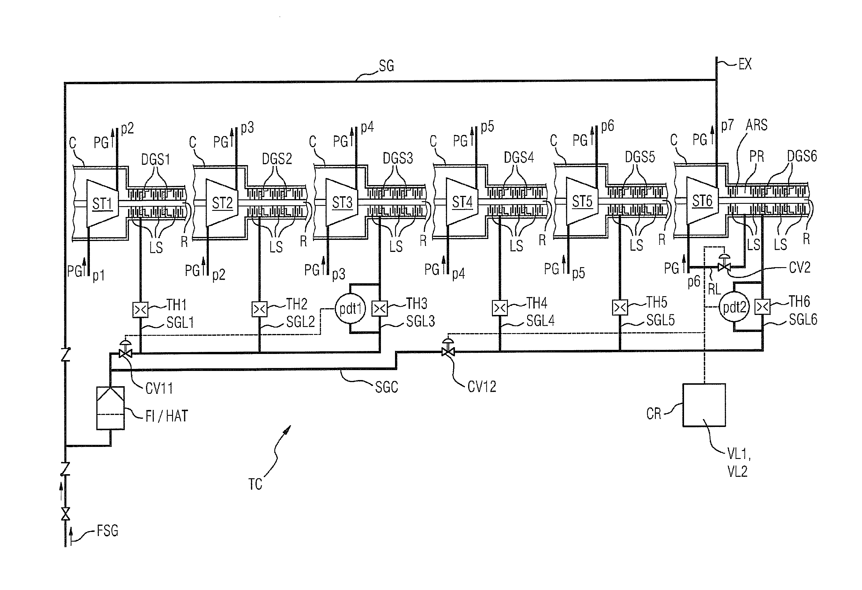
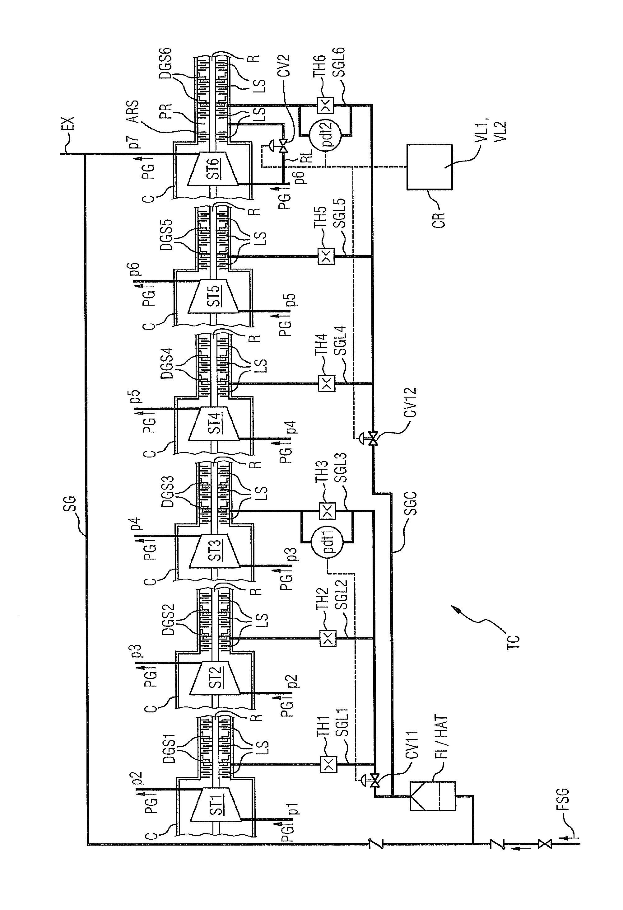
[0006]Based on the previously described problems of the prior art, the invention is based on the object of creating improved sealing of multistage turbocompressors, which prevents the gas seals being exposed to the action of unfiltered process gas.
[0008]The relieving according to the invention of the pressure chamber on the pressure side of the gas seal ensures the necessary
pressure difference in order to ensure the sealing effect or to ensure an inflow of sealing gas for the supply of the gas seal through the sealing gas line, especially in operating states which are characterized by an only low pressure build up in the multistage turbocompressor. The relief line is preferably dimensioned in such a way that the achieved pressure drop in the pressure chamber on the pressure side of the gas seal is sufficient for adequate sealing gas to flow in and for no process gas to find its way to the gas seal. Furthermore, the
dimensioning be such that no more sealing gas is consumed than is necessary for achieving the sealing effect and for reliable operation. A discharge into a stage of the turbocompressor where a lower pressure exists than in the pressure chamber is preferably as a pressure sink. The discharge into an inlet into a stage is especially expedient in this case. In this way, the process gas is circulated at an only low rate for the purpose of the intended pressure relief. In order to minimize as far as possible the consumption of pre-pressurized process gas or to minimize the portion of process gas which is expanded as a result of the pressure relief, it is expedient if an additional shaft seal is provided between the pressure chamber and a stage exit of the associated stage. This is preferably designed as a
labyrinth seal. This additional shaft seal can bring about a necessary pressure loss which is required so that the sealing gas, if it is tapped from the highest-pressure stage, has the
pressure difference so that it flows into the gas seal.
[0010]An especially preferred field of application of the invention are turbocompressors in which a plurality of stages have at least one gas seal in each case, especially where a plurality of stages are provided in different casings which have in each case a gas seal at a penetration of the shaft through a casing wall. For minimizing the sealing
gas consumption, it is also expedient if the sealing gas line, which is connected in each case to the gas seal, has a
throttle valve or an adjustable valve by means of which the sealing
gas pressure which is present at the seal during normal operation is set in such a way that the gas seal can properly fulfill its function and the consumption of sealing gas is minimized at the same time. A certain pressure reserve should be made available in this case in order to be able to pass through anticipated fluctuations of the operating state in an error-free manner.
[0011]The sealing gas lines of the individual gas seals are advantageously connected to a sealing gas
feed line or to a sealing gas header. Between the individual junctions of the sealing gas lines, this sealing gas
feed line can be provided with
control valves which, in dependence upon the operating state, lowers the pressure in the downstream sealing gas lines. In this way, in addition to the static
throttle in the sealing gas line, there is preferably an adjustability of the sealing gas feed, which in certain operating states counteracts an excessive consumption of sealing gas. On the other hand, this use of
control valves enables the provision of a reserve which in case of need ensures the
operational reliability of the gas seals. In particular, in combination with the relief lines according to the invention, the sealing
gas consumption can thus be minimized on the one hand and on the other hand the
operational reliability of the gas seals can be increased.
[0012]A valve which opens in case of need can be especially advantageously provided in the relief lines. This valve can be designed with a binary positioning option or can be gradually adjustable as a control valve, which second option additionally offers the opportunity—in the case of a relief requirement—to adapt the extent of the pressure relief to the actual requirement and at the same time not to excessively impair the efficiency of the overall arrangement.
[0013]A preferred central
control unit can expediently control both the position of the
control valves in the sealing gas feed line and that of the valves in the relief line, especially in dependence upon the volumetric flow in the sealing gas line. For this purpose, it is advisable to directly or indirectly measure the volumetric flow in the sealing gas lines. Reliable measuring can be carried out by means of a measuring arrangement at the throttles or adjustable valves in the sealing gas lines, which can deter mine the pressure difference there, which can allow a clear conclusion to be drawn about the volumetric flow. The
control unit opens the control valve, or control valves, in the sealing gas feed line if the measurement for the volumetric flow through the sealing gas line of at least one gas seal falls below a first volumetric-flow
limit value. Furthermore, the
control unit opens the valves in the relief lines collectively or individually if an excessively low volumetric flow is determined at the respective measuring point in the sealing gas line, or an excessively low volumetric flow is determined at least one measuring point in a sealing gas line.

