Brake caliper seal groove

a technology of seal grooves and brake calipers, applied in the direction of mechanical equipment, engine components, metal working equipment, etc., can solve the problems of reducing the life of brake pads and rotors, and increasing fuel consumption, so as to reduce the cost of sealing, clean the seal, and the effect of easy and smooth sealing

Inactive Publication Date: 2012-04-19
AKEBONO BRAKE
View PDF4 Cites 8 Cited by
  • Summary
  • Abstract
  • Description
  • Claims
  • Application Information

AI Technical Summary

Benefits of technology

[0041]The first angled wall and the second angled wall may form an angle between them. The angle formed between the first angled wall. and the second angled wall may be any angle capable of forming a peak that may cut the seal. The peak may be any angle that forms a sharp edge (i.e. has enough material thickness) so that the peak cuts the seal. The peak may be any angle that is rigid enough that it will not fracture, break, or become damaged from repeated contact with the seal during brake applies. Preferably, the angle of the peak may have enough material so that the peak cuts the seal and does not deform during multiple uses. The peak may be any angle that is sufficiently steep so that the seal is easily and smoothly cut. Preferably, the peak may be an angle that is sharp so that the peak does not nibble away at the seal during repeated use. The angle formed between the first angled wall and the second angled wall may be about 140 degrees or less. Preferably, the angle between the first angled wall and second angled wall may be about 110 degrees or less. More preferably, the angle between the first angled wall and the second angled wall may be about 95 degrees or less.
[0042]The first angled wall and the second angled wall may form a blunt peak (i.e. point that does not form a. sharp angle). The blunt peak may cut the seal. The blunt peak may create a clean cut in the seal. The blunt peak may reduce and / or eliminate seal nibble. The blunt peak may include a blunt wall that connects the first angled wall to the second angled wall. The blunt wall may be about 0.1 mm or less, about 0.05 mm or less, or about 0.005 mm or less in length. The blunt wall may be any length that cuts the seal. The blunt wall may be at any orientation that allows the blunt peak to cut a seal. The blunt wall may form a flat surface; for example, the first wall and the second wall may connect to the blunt wall at the same height so that it is substantially perpendicular to the seal. The blunt wall may form an angled surface; for example, the first wall and the second wall may connect to the blunt wall at different heights so that the blunt wall forms an angle relative to the seal. The, blunt wall may form any angle that allows the blunt peak to cut the seal. The blunt wall may form about a 45 degree angle or more, preferably about a 60 degree angle or more, or more preferably about a 90 degree angle relative to the front wall. The blunt wall may form about a 150 degree angle or less, about a 135 degree angle or less, preferably about a 110 degree angle or less relative to the front wall.

Problems solved by technology

However, if the piston retraction is too small, the piston remains in contact with the brake pad which in turn remains in contact with the rotor.
A small brake drag is, therefore, maintained which results in increased fuel consumption and reduced brake pad and rotor life, or both.
If the piston retraction is too large, a large air gap is created between the piston and the brake pad, thus resulting in a longer brake pedal travel.
The longer brake pedal travel will result in a poor pedal feel and possibly even customer complaints.
More recently, reduced fuel consumption has become an increasingly important challenge among vehicle manufacturers and vehicle owners.
One factor that affects fuel consumption is brake drag caused by contact forces between one or more brake pads and the vehicle's rotor due to insufficient piston retraction distance.
One challenge faced by brakes is providing a brake where, after a brake apply, the piston returns to its pre-brake position regardless of the brake pressure applied during braking.
Another challenge faced by brakes is how to optimize the air gap (i.e. running clearance).
For example, a large air gap causes the brake to feel soft; whereas, a small air gap may cause an increased drag torque.
Another challenge faced is deterioration of the seal with repeated use, thus, affecting piston retraction.

Method used


Image

  • Brake caliper seal groove
  • Brake caliper seal groove
  • Brake caliper seal groove

Examples


Embodiment Construction

[0020]The following description of the preferred embodirnent(s) is merely exemplary in nature and is in no way intended to limit the invention, its application, or uses.

[0021]The present invention is predicated upon providing an improved disc brake system and caliper for use with vehicles. For example, the caliper may be used with almost any vehicle (e.g. car, truck, bus, train, airplane, or the like). Alternatively, the caliper may be integrated into assemblies used for manufacturing or other equipment that require a brake such as a lathe, winder for paper products or cloth, amusement park rides, or the like. However, the present invention is most suitable for use with a passenger vehicle (i.e. a car, truck, sports utility vehicle, or the like).

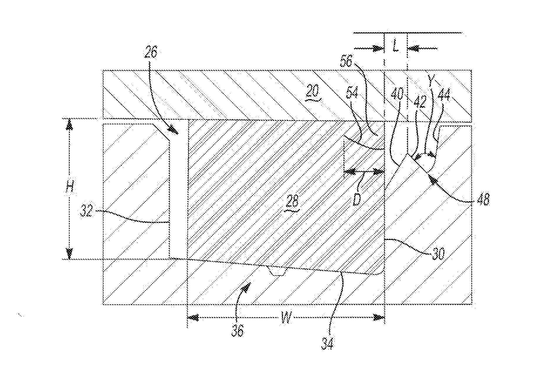
[0022]Generally, a braking system includes a rotor, a caliper body, a support bracket, an inboard brake pad, and an outboard brake pad that are on opposing sides of the rotor. The caliper body further includes a bridge, one or more fingers, ...


PUM

PropertyMeasurementUnit
angleaaaaaaaaaa
radiusaaaaaaaaaa
angleaaaaaaaaaa

Abstract

A seal groove comprising: a back wall; a front wall opposed to the back wall; a bottom wall connected to the front wall and the back wall; and a recess in the front wall connecting the front wall to the piston bore; wherein the recess includes a peak which comprises: a first angled portion and a second angled portion.

Description

FIELD OF THE INVENTION[0001]The present invention generally relates to seals, seal grooves, pistons, and more particularly to an angled wall of the seal groove and a pre-cut or a cutable seal that is especially suited for use in a brake assembly.BACKGROUND OF THE INVENTION[0002]Typical disc brake systems involve a caliper which, during brake apply, develops a clamping force against brake pads in the wheel axial direction onto an annular braking path on the rotor. The clamping force is created during a brake apply by increasing fluid pressure in the piston bore of the caliper body, which forces the piston towards the rotor. Brake fluid leakage is prevented by a seal installed between the caliper body and the piston. The seal is located inside a groove (i.e. the annular seal groove) that is machined into the piston bore of the caliper body. The seal, seal groove, and piston dimensions are such that when the piston is inserted into the bore, an interference fit between the seal, which ...

Claims


Application Information

Patent Timeline
Patent Type & Authority Applications(United States)
IPC IPC(8): F16J15/16F16D65/20B26D3/06
CPCF16J15/3272Y10T83/0304
Inventor CHELAIDITE, GALUSLOU, GANG
Owner AKEBONO BRAKE
Why Eureka
Try Eureka