A stainless steel pipe bevel cutting machine

A technology of stainless steel pipe and cutting machine, which is applied in the direction of metal processing machinery parts, clamping, support, etc., can solve the problems of waste of resources, uneven cutting section, and scrapping of rectangular steel pipes, so as to reduce the probability of deviation and improve Work efficiency, increase control effect

Active Publication Date: 2020-05-12
浙江德瑞不锈钢有限公司
View PDF8 Cites 0 Cited by
  • Summary
  • Abstract
  • Description
  • Claims
  • Application Information

AI Technical Summary

Problems solved by technology

[0006] The present invention can solve the problem that when cutting the bevel of the existing rectangular steel pipe, the inclination angle of the cutting knife and the required inclination angle of the steel pipe usually have a large deviation, resulting in poor cutting quality During the cutting process of rectangular steel pipes, it is easy to deviate, which leads to a part of the cutting part on the rectangular steel pipes not being cut, resulting in discontinuous cutting, resulting in uneven cutting sections, which affects the quality of the cutting sections and the subsequent use of rectangular steel pipes. When the steel pipe is cut on a bevel, because the rectangular steel pipe is a hollow structure, the steel pipe near the cutting place tends to sag and wrinkle inward when cutting the bevel, which causes the rectangular steel pipe here to be scrapped and wastes resources. At the same time, the existing rigid clamp is usually used The rectangular steel pipe is fixed and assisted in transportation by holding the rectangular steel pipe. The friction between the rectangular steel pipe and the rigid clamping structure is relatively large, which is prone to increased wear and deformation, and affects the processing quality of the rectangular steel pipe.

Method used


Image

  • A stainless steel pipe bevel cutting machine
  • A stainless steel pipe bevel cutting machine
  • A stainless steel pipe bevel cutting machine

Examples


Embodiment Construction

[0033] The embodiments of the present invention will be described in detail below in conjunction with the accompanying drawings, but the present invention can be implemented in many different ways that are predetermined and covered by the claims.

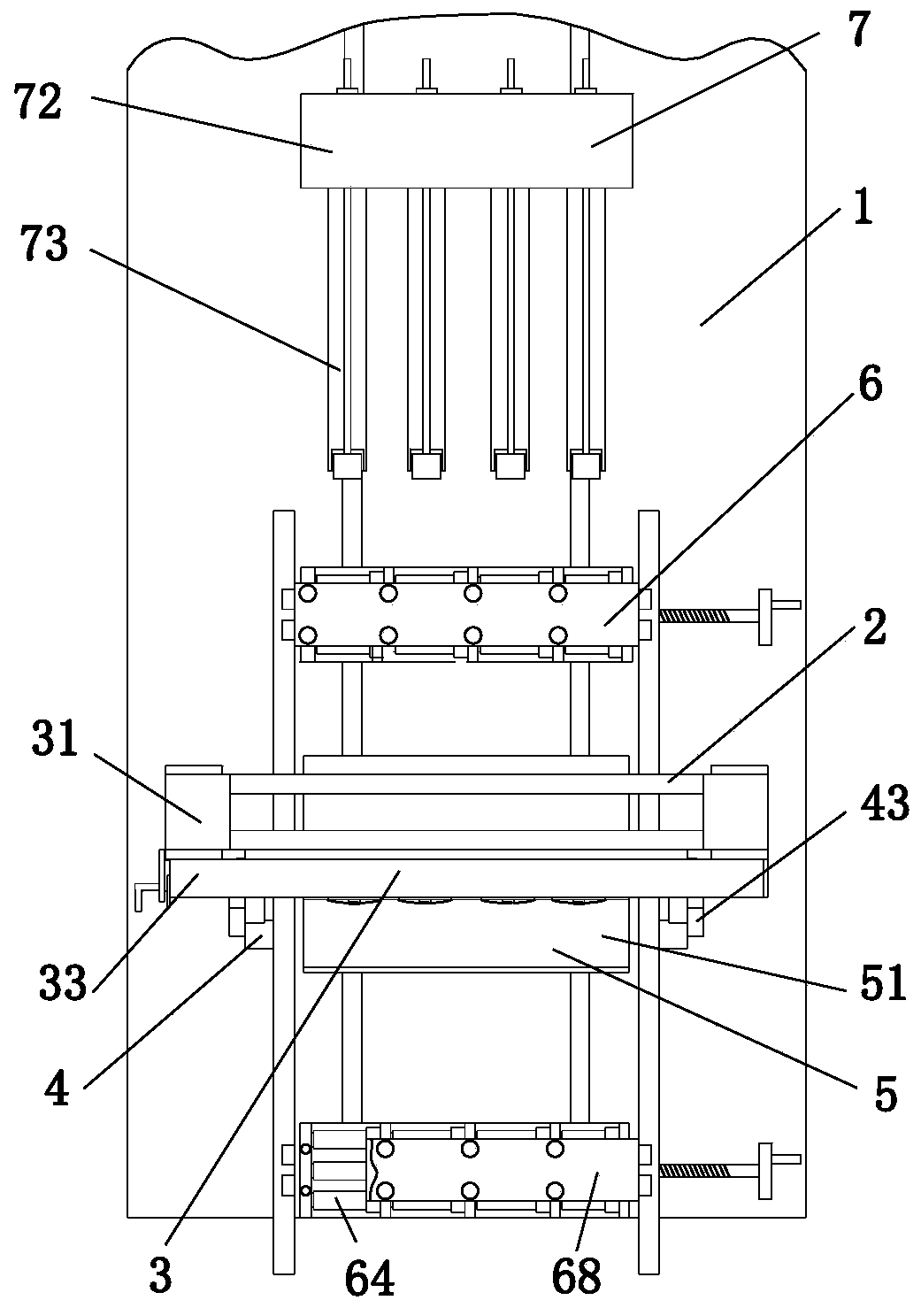
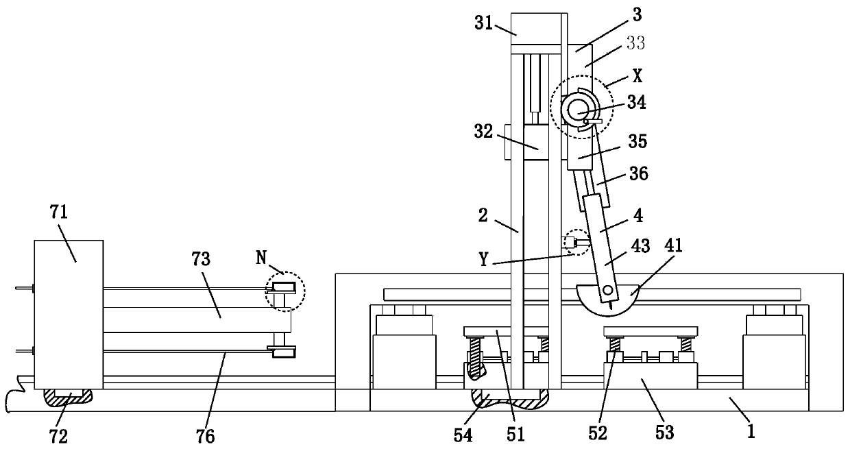
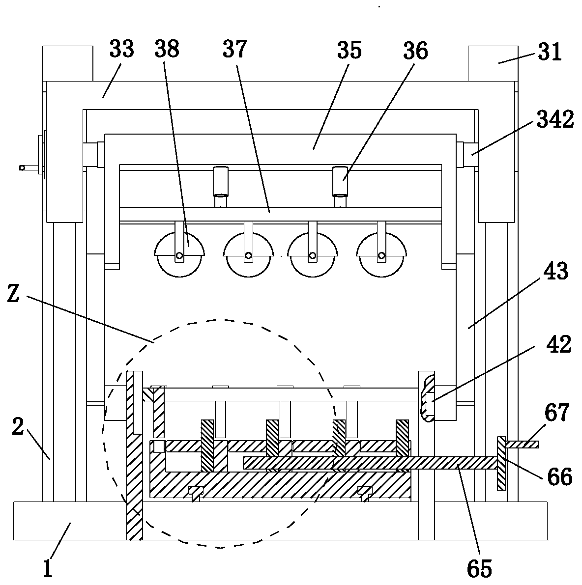
[0034] Such as Figure 1 to Figure 7 As shown, a stainless steel pipe bevel cutting machine includes a workbench 1, a gantry 2, a cutting device 3, a guide device 4, a carrying device 5, a clamping device 6 and a support device 7, and the gantry is installed on the workbench 1 2. The cutting device 3 is installed on the gantry 2 through a sliding fit, and the guide device 4 is arranged symmetrically on the left and right sides of the upper end of the workbench 1. The guide device 4 is located on the front side of the gantry 2, and the middle part of the upper end of the workbench 1 is symmetrical front and rear A bearing device 5 is installed, and the upper end of the workbench 1 is symmetrically installed with a clamping device 6 f...


PUM


Abstract

The invention relates to a stainless steel pipe groove cutting machine. The stainless steel pipe groove cutting machine comprises a workbench, a portal frame, a cutting device, guide devices, bearingdevices, clamping devices and a support device. The portal frame is mounted on the workbench. The cutting device is mounted on the portal frame in a sliding fit mode. The left side and the right sideof the upper end of the workbench are symmetrically provided with the guide devices. The guide devices are located on the front side of the portal frame. The front portion and the rear portion of themiddle of the upper end of the workbench are provided with bearing devices symmetrically front and back. The clamping devices are mounted at the upper end of the workbench in a sliding fit mode symmetrically front and back. The bearing devices are located between the two clamping devices. The support device is arranged on the rearmost side of the upper end of the workbench in a sliding fit mode. The phenomena that when rectangular steel pipe bevels are cut at present, the inclination angle of a cutting blade is severely deviated from the required on inclination angle on steel pipes, the cutting quality is poor, and the cutting blade is prone to deflecting during the cutting process of the rectangular steel pipe can be avoided.

Description

technical field [0001] The invention relates to the field of cutting machines, in particular to a bevel cutting machine for stainless steel pipes. Background technique [0002] Steel pipe cutting machine is an electric mechanical equipment that can cut and notch various construction steel materials such as stainless steel and bearing steel. , the steel pipe cutting machine has the characteristics of wide application range, good processing surface quality, etc., and can perform surface cutting and groove processing at various angles. Nowadays, steel pipe cutting machines are often used to cut rectangular steel pipes of different sizes. The following problems occur during bevel cutting: [0003] 1. When cutting rectangular steel pipe bevels, usually the inclination angle of the cutting knife and the required inclination angle of the steel pipe will have a large deviation, resulting in poor cutting quality, and the cutting knife is prone to deviation during the cutting process...

Claims


Application Information

Patent Timeline
Patent Type & Authority Patents(China)
IPC IPC(8): B23D79/00B23Q3/06B23Q1/26B23Q5/34
CPCB23D79/00B23Q1/26B23Q3/064B23Q5/34
Inventor 黄伟付子豪
Owner 浙江德瑞不锈钢有限公司
Why Eureka
Try Eureka