Bevel cutter for rectangular steel tube

A technology for rectangular steel pipes and cutting machines, applied to metal processing machinery parts, large fixed members, clamping, etc., can solve problems such as waste of resources, uneven cutting sections, deviation, etc., to reduce the probability of deviation, Improve work efficiency and improve quality

Inactive Publication Date: 2020-01-10
宣城久悠谷电子科技有限公司
View PDF7 Cites 2 Cited by
  • Summary
  • Abstract
  • Description
  • Claims
  • Application Information

AI Technical Summary

Problems solved by technology

[0006] The present invention can solve the problem that when cutting the bevel of the existing rectangular steel pipe, the inclination angle of the cutting knife and the required inclination angle of the steel pipe usually have a large deviation, resulting in poor cutting quality During the cutting process of rectangular steel pipes, it is easy to deviate, which leads to a part of the cutting part on the rectangular steel pipes not being cut, resulting in discontinuous cutting, resulting in uneven cutting sections, which affects the quality of the cutting sections and the subsequent use of rectangular steel pipes. When the steel pipe is cut on a bevel, because the rectangular steel pipe is a hollow structure, the steel pipe near the cutting place tends to sag and wrinkle inward when cutting the bevel, which causes the rectangular steel pipe here to be scrapped and wastes resources. At the same time, the existing rigid clamp is usually used The rectangular steel pipe is fixed and assisted in transportation by holding the rectangular steel pipe. The friction between the rectangular steel pipe and the rigid clamping structure is relatively large, which is prone to increased wear and deformation, and affects the processing quality of the rectangular steel pipe.

Method used


Image

  • Bevel cutter for rectangular steel tube
  • Bevel cutter for rectangular steel tube
  • Bevel cutter for rectangular steel tube

Examples


Embodiment Construction

[0033] The embodiments of the present invention will be described in detail below with reference to the accompanying drawings, but the present invention can be implemented in many different ways as defined and covered by the claims.

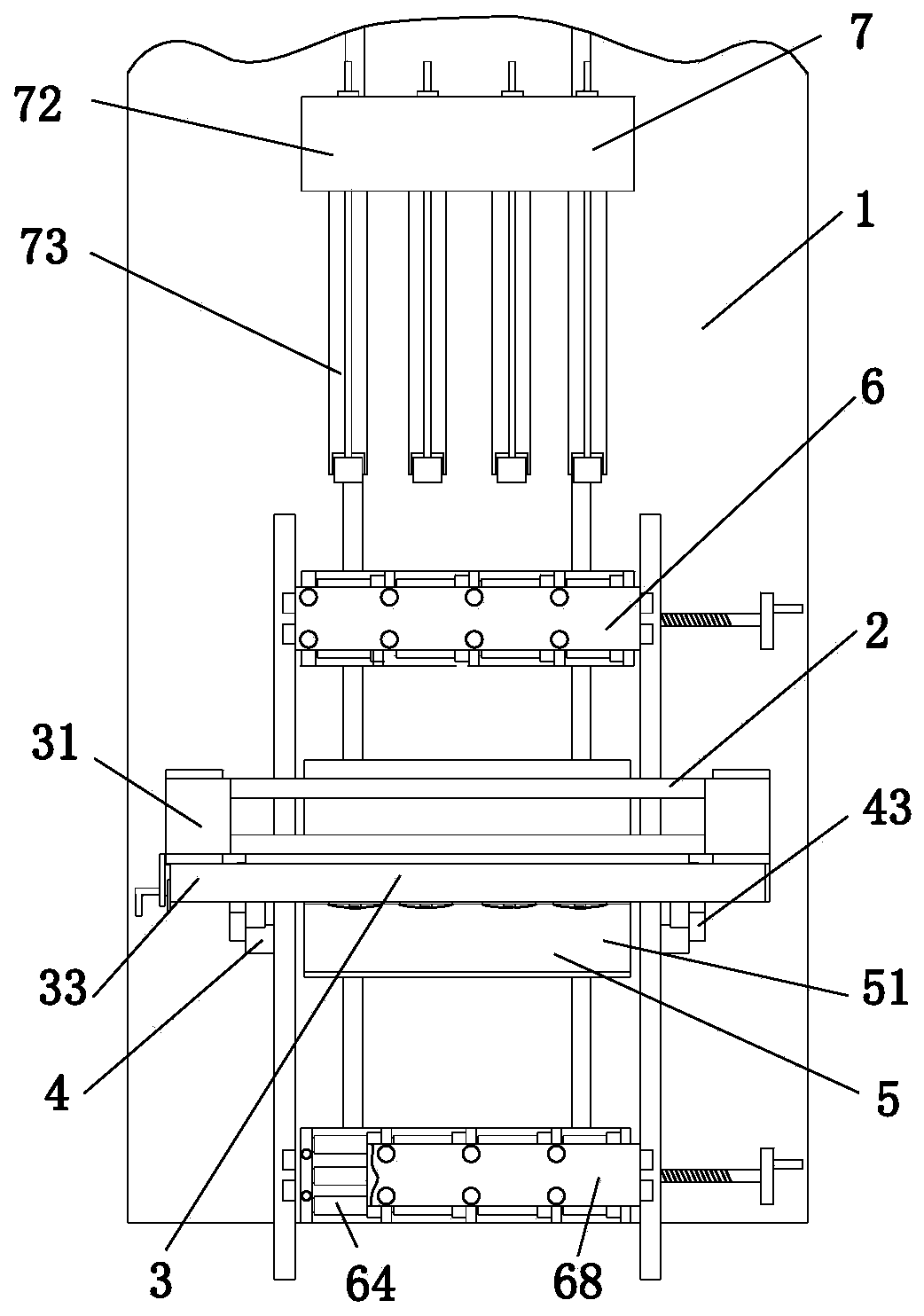
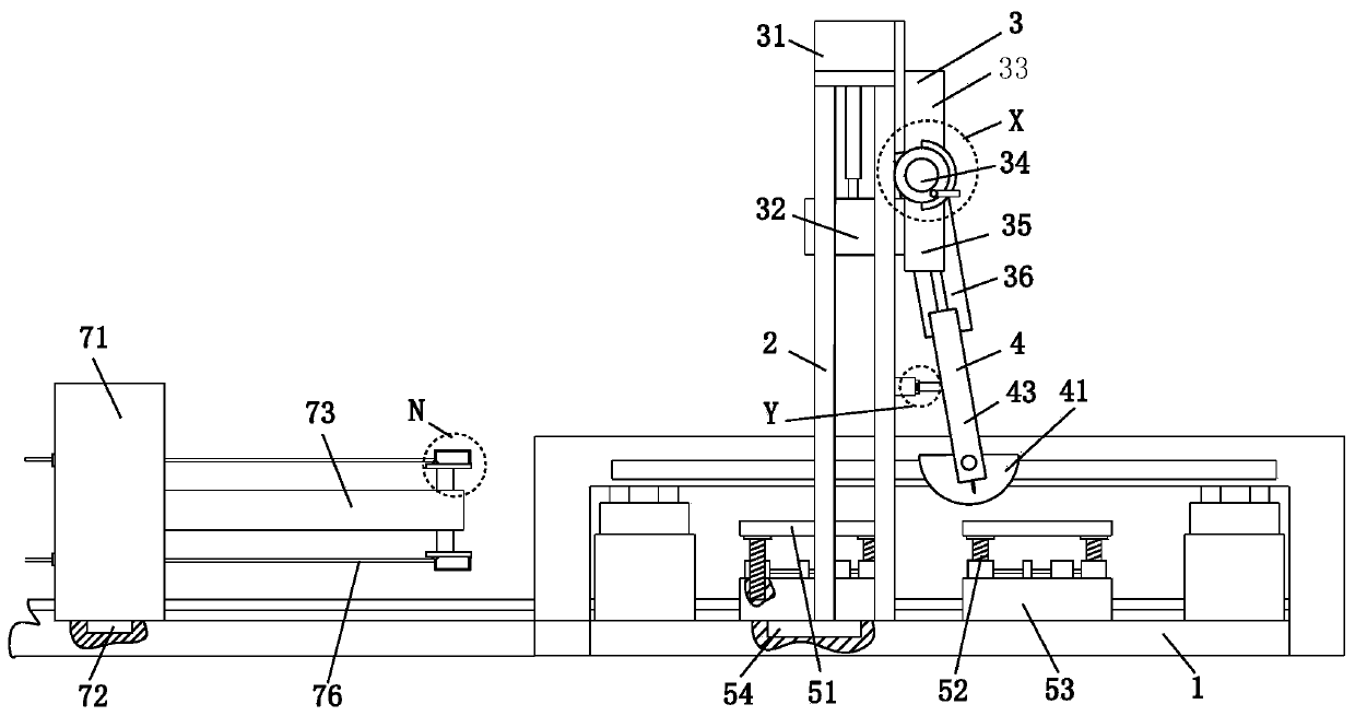
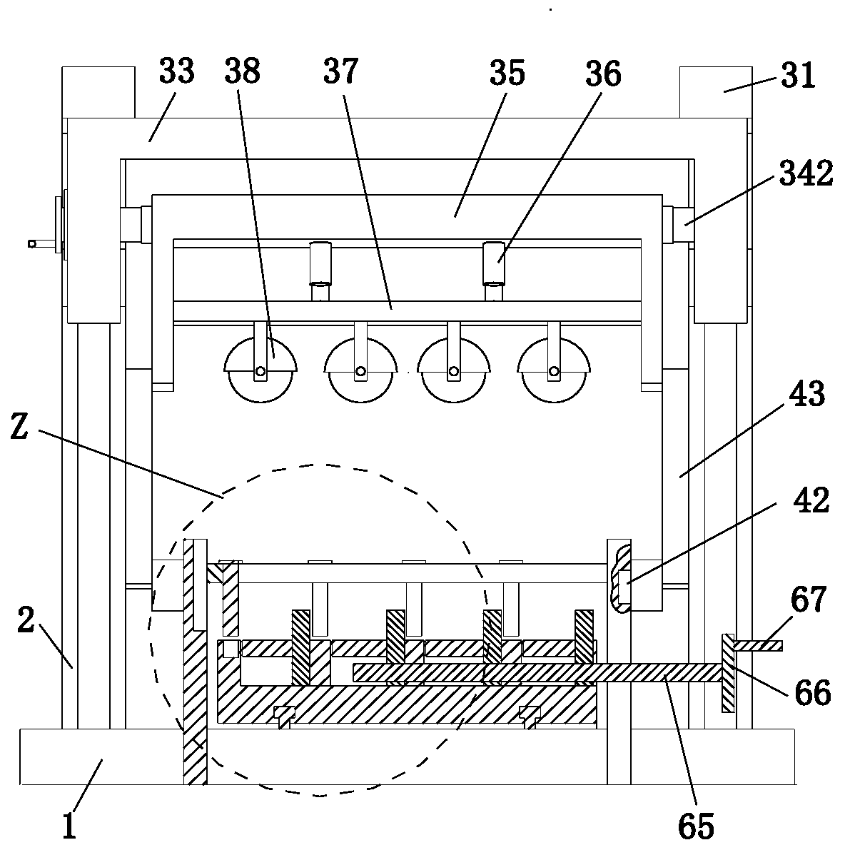
[0034] Such as Figure 1 to Figure 7 As shown, a bevel cutting machine for rectangular steel pipes includes a workbench 1, a gantry frame 2, a cutting device 3, a guide device 4, a carrying device 5, a clamping device 6 and a support device 7, and a gantry is installed on the workbench 1 Frame 2, cutting device 3 is installed on the gantry frame 2 through a sliding fit, guide devices 4 are symmetrically arranged on the left and right sides of the upper end of the workbench 1, and the guide device 4 is located on the front side of the gantry frame 2. The carrying device 5 is symmetrically installed, the upper end of the workbench 1 is symmetrically installed with the clamping device 6 front and rear through the sliding fit method, and the carrying...


PUM


Abstract

The invention relates to a bevel cutter for a rectangular steel tube. The bevel cutter comprises a workbench, a portal frame, a cutting device, a guide device, bearing devices, clamping devices and asupporting device, wherein the portal frame is mounted on the workbench; the cutting device is mounted on the portal frame in a sliding fit mode; the left and right sides of the upper end of the workbench are symmetrically equipped with guide devices; the guide devices are positioned at the front end of the portal frame; front and rear sides of the middle part of the upper end of the workbench aresymmetrically equipped with the bearing devices; front and rear sides of the upper end of the workbench are symmetrically equipped with clamping devices in the sliding fit mode; the bearing devices are positioned between the two clamping devices; and the rearmost side of the upper end of the workbench is equipped with the supporting device in the sliding fit mode. The bevel cutter can solve the problems that cutting quality is not good as an inclination angle of a cutting knife and a needed inclination angle on the steel tube generate relatively great deviation while bevel cutting is performed on an existing rectangular steel tube, and the cutting knife is liable to have an off-tracking phenomenon in a rectangular steel tube cutting process.

Description

technical field [0001] The invention relates to the field of cutting machinery, in particular to a bevel cutting machine for rectangular steel pipes. Background technique [0002] Steel pipe cutting machine is an electric mechanical equipment that can cut and notch various construction steel materials such as stainless steel and bearing steel. , the steel pipe cutting machine has the characteristics of wide application range, good processing surface quality, etc., and can perform surface cutting and groove processing at various angles. Nowadays, steel pipe cutting machines are often used to cut rectangular steel pipes of different sizes. The following problems occur during bevel cutting: [0003] 1. When cutting rectangular steel pipe bevels, usually the inclination angle of the cutting knife and the required inclination angle of the steel pipe will have a large deviation, resulting in poor cutting quality, and the cutting knife is prone to deviation during the cutting proc...

Claims


Application Information

Patent Timeline
Patent Type & Authority Applications(China)
IPC IPC(8): B23Q1/25B23Q15/26B23Q3/06B23Q3/00
CPCB23Q1/25B23Q3/00B23Q3/06B23Q3/062B23Q3/064B23Q15/26
Inventor 林明辉
Owner 宣城久悠谷电子科技有限公司
Why Eureka
Try Eureka