
Pre-ignition estimation/control device for an internal combustion engine

a technology of estimation/control device and internal combustion engine, which is applied in the direction of electric control, machines/engines, instruments, etc., can solve the problems of internal combustion engine may finally become no longer operable, noise and vibration, and noise and vibration, and achieve indirect restriction of the effect of effective compression ratio

Active Publication Date: 2012-04-12
MITSUBISHI ELECTRIC CORP
View PDF3 Cites 19 Cited by
  • Summary
  • Abstract
  • Description
  • Claims
  • Application Information

AI Technical Summary

Benefits of technology

[0013]In order to solve the above-mentioned problems, the present invention has been made, and it is therefore an object of the present invention to provide a pre-ignition estimation / control device for an internal combustion engine which calculates a pre-ignition occurrence index indicating a likelihood of pre-ignition from an intake air temperature, a coolant temperature, and an octane number of a fuel, and controls an intake-cam variable phasing system based on the pre-ignition occurrence index so as to restrict a phase change (change in phase advance) of an intake cam across an entire operation state, to thereby prevent the pre-ignition.
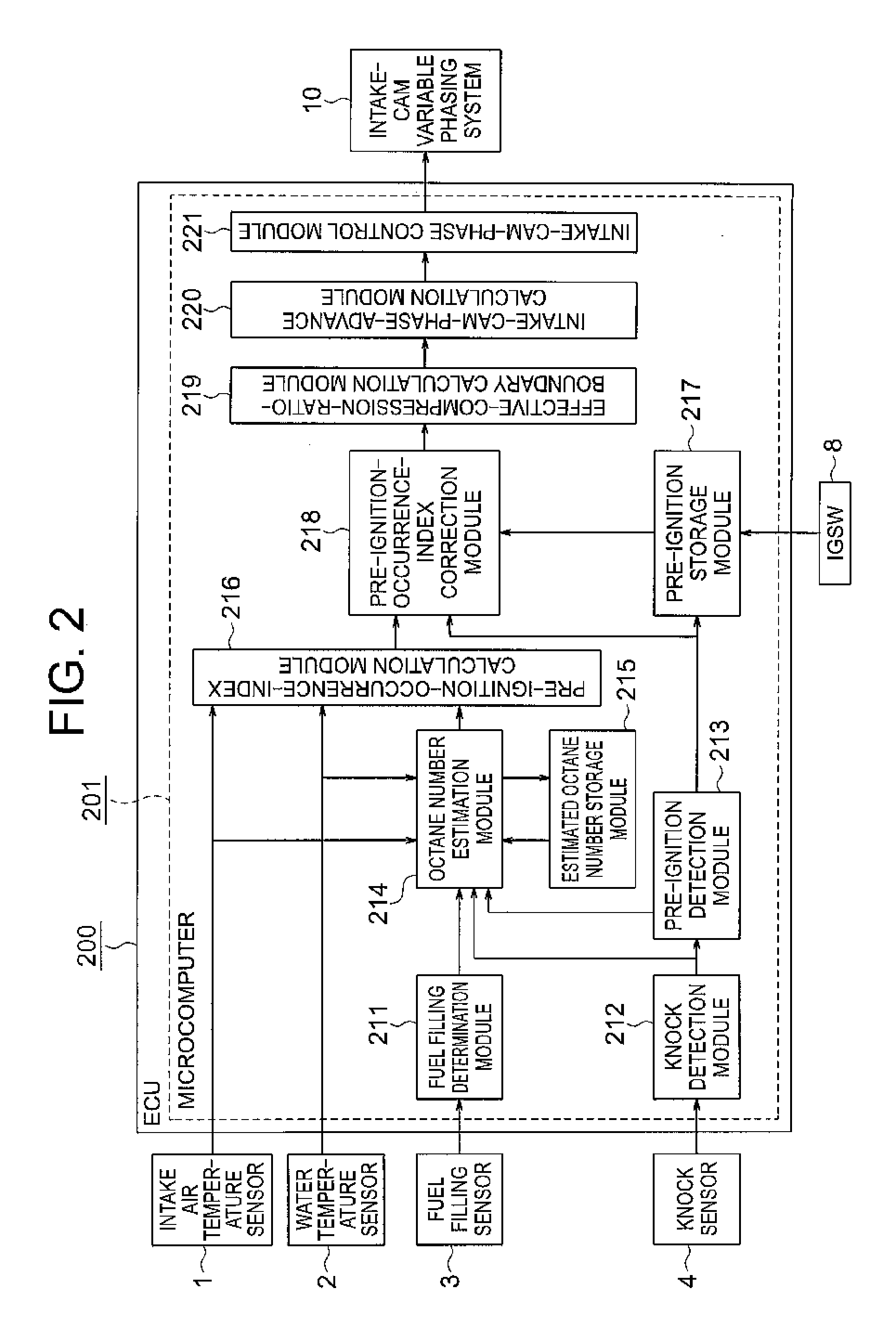
[0014]The present invention provides a pre-ignition estimation / control device for an internal combustion engine, including: an intake air temperature sensor for detecting a temperature of intake air to be introduced into a combustion chamber; a water temperature sensor for detecting a coolant temperature of the internal combustion engine; a fuel filling sensor for detecting a flow of a fuel in a fuel filler opening; knock detection means for detecting a change of the internal combustion engine caused by a knock and pre-ignition; an intake-cam variable phasing system for changing opening / closing timings of an intake valve by changing a phase of an intake cam; octane number estimation means for estimating an octane number of the fuel based on detection signals received from the intake air temperature sensor, the water temperature sensor, the fuel filling sensor, and the knock detection means; a pre-ignition-occurrence-index calculation module for calculating a total pre-ignition occurrence index based on the detection signals received from the intake air temperature sensor and the water temperature sensor, and the octane number estimated by the octane number estimation means; a pre-ignition-occurrence-index correction module for correcting, when the pre-ignition is detected, the total pre-ignition occurrence index so as to cause the pre-ignition more likely to occur; an effective-compression-ratio-boundary calculation module for calculating a boundary of an effective compression ratio based on the total pre-ignition occurrence index obtained by the pre-ignition-occurrence-index correction module; an intake-cam-phase-advance calculation module for calculating a phase advance of the intake cam based on an operation condition and the boundary of the effective compression ratio calculated by the effective-compression-ratio-boundary calculation module; and an intake-cam-phase control module for controlling the intake-cam variable phasing system based on the phase advance of the intake cam output from the intake-cam-phase-advance calculation module, to thereby restrict a change in the phase advance of the intake cam.
[0015]According to the pre-ignition estimation / control device for an internal combustion engine of the present invention, the intake-cam variable phasing system is controlled based on the pre-ignition occurrence index so as to restrict the phase change (change in phase advance) of the intake cam across the entire operation state and the effective compression ratio is indirectly restricted, to thereby prevent the pre-ignition.

Problems solved by technology

Pre-ignition causing combustion noises and fluctuations in output may occur in a high-compression-ratio spark-ignition internal combustion engine.
These phenomena cause noises and vibrations as well as damages in the combustion chamber of the internal combustion engine, and the internal combustion engine may finally become no longer operable.
However, causes of the occurrence of the pre-ignition include fuel properties in addition to the temperature in the internal combustion engine and the increase in temperature caused by the compression in the combustion chamber, and it is known that the pre-ignition occurs more frequently as the octane number of the fuel becomes low.
The opposite holds true, and even if the octane number is high, high environmental temperature possibly causes pre-ignition.
However, Japanese Patent Application Laid-open No. 2009-114973 describes only the prevention of the pre-ignition that occurs on the startup (prevention of the pre-ignition refers to prevention of such an operation state that possibly causes the pre-ignition), and does not consider pre-ignition which occurs “after the startup”.
Moreover, Japanese Patent Application Laid-open No. 2009-114973 does not consider a method of avoiding pre-ignition after the preventive operation of the pre-ignition (avoidance of pre-ignition refers to a change of an operation state to prevent pre-ignition from occurring any more when pre-ignition actually occurs).
However, even if a fuel having a high octane number (high octane fuel of 95 [RON], for example) is used, it is experimentally known that pre-ignition may occur at high intake air temperature and high water temperature.

Method used


Image

  • Pre-ignition estimation/control device for an internal combustion engine
  • Pre-ignition estimation/control device for an internal combustion engine
  • Pre-ignition estimation/control device for an internal combustion engine

Examples


first embodiment

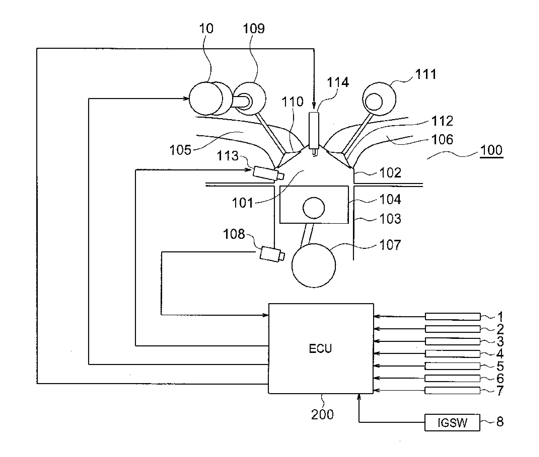
[0033]Referring to FIGS. 1 to 14, a description is given of the pre-ignition estimation / control device for an internal combustion engine according to a first embodiment of the present invention. FIG. 1 is a diagram illustrating a schematic configuration of the internal combustion engine according to the first embodiment of the present invention. It should be noted that like and corresponding components are denoted by like numerals throughout the drawings in the following section.

[0034]In FIG. 1, a combustion chamber 101 of an internal combustion engine 100 is constructed by a cylinder head 102, a cylinder block 103, and a piston 104.

[0035]Further, an intake port 105 and an exhaust port 106 are connected to the combustion chamber 101, and the intake port 105 and the exhaust port 106 are formed on the cylinder head 102.

[0036]A crank shaft 107 is connected to the piston 104, and the crank shaft 107 is rotated by a vertical motion of the piston 104. A crank plate (not shown) is attached...


PUM


Abstract

A pre-ignition estimation / control device includes: an octane number estimation module for estimating an octane number of a fuel based on detection signals received from an intake air temperature sensor, a water temperature sensor, etc; a pre-ignition-occurrence-index calculation module for calculating a pre-ignition occurrence index based on the estimated octane number and the like; a pre-ignition-occurrence-index correction module for correcting the pre-ignition occurrence index so as to cause the pre-ignition more likely to occur; an effective-compression-ratio-boundary calculation module for calculating a boundary of an effective compression ratio based on the pre-ignition occurrence index; an intake-cam-phase-advance calculation module for calculating a phase advance of an intake cam based on the boundary of the effective compression ratio and the like; and an intake-cam-phase control module for controlling an intake-cam variable phasing system based on the phase advance of the intake cam, to thereby restrict a change in phase advance.

Description

BACKGROUND OF THE INVENTION[0001]1. Field of the Invention[0002]The present invention relates to a pre-ignition estimation / control device for an internal combustion engine, which is installed on a vehicle or the like and can prevent pre-ignition.[0003]2. Description of the Related Art[0004]Pre-ignition causing combustion noises and fluctuations in output may occur in a high-compression-ratio spark-ignition internal combustion engine. The pre-ignition refers to a phenomenon of an excessively large fluctuation in pressure inside a combustion chamber of an internal combustion engine, which results from combustion. Pre-ignition which occurs before the spark ignition is generally known. In addition to this type of pre-ignition, there are phenomena including pre-ignition in which a mixture (mixed gas of the air and a fuel) in the combustion chamber reaches high temperature by compression and is auto-ignited, and pre-ignition in which a deposit or the like at a tip of a spark plug forms a ...

Claims


Application Information

Patent Timeline
Patent Type & Authority Applications(United States)
IPC IPC(8): F02D43/00
CPCF02D13/0238F02D35/027F02D41/0025Y02T10/18F02D2200/021F02D2200/0414F02D2200/0612F02D2041/001Y02T10/12
Inventor MAKINO, TOMOKAZUHAGARI, HIDEKI
Owner MITSUBISHI ELECTRIC CORP
Learn More