
Enhanced packing of energy storage particles

a technology of energy storage particles and energy storage particles, which is applied in the field of packaging of energy storage particles, can solve the problems of limited physical size of electrodes, insufficient current application of such methods, and inconvenient size of electrodes, and achieve the effect of improving volumetric performan

Inactive Publication Date: 2012-04-05
BASF AG
View PDF7 Cites 81 Cited by
  • Summary
  • Abstract
  • Description
  • Claims
  • Application Information

AI Technical Summary

Benefits of technology

[0012]In general terms, the present invention is directed to energy storage materials comprising a plurality of energy storage particles. In one particular embodiment, the energy storage material is activated carbon and the energy storage particles are activated carbon particles. In this embodiment, the plurality of carbon particles comprises a particle size distribution such that particle packing is optimized r...

Problems solved by technology

For example, in many of the devices described above, size is a constraint, and the physical size of the electrode is limited.
While these methods may improve the particle packing over the unprocessed carbon material, current applications of such methods are not sufficient to provide an activated carbon material having a particle size distribution which provides for optimized particle packing.

Method used


Image

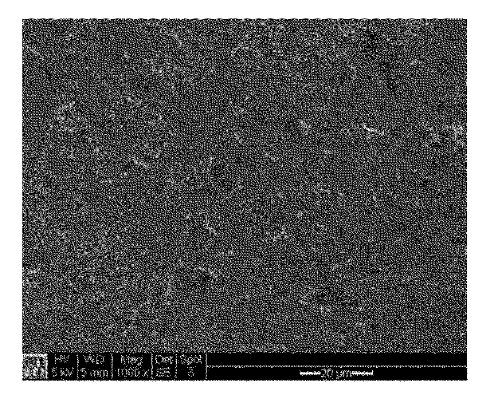
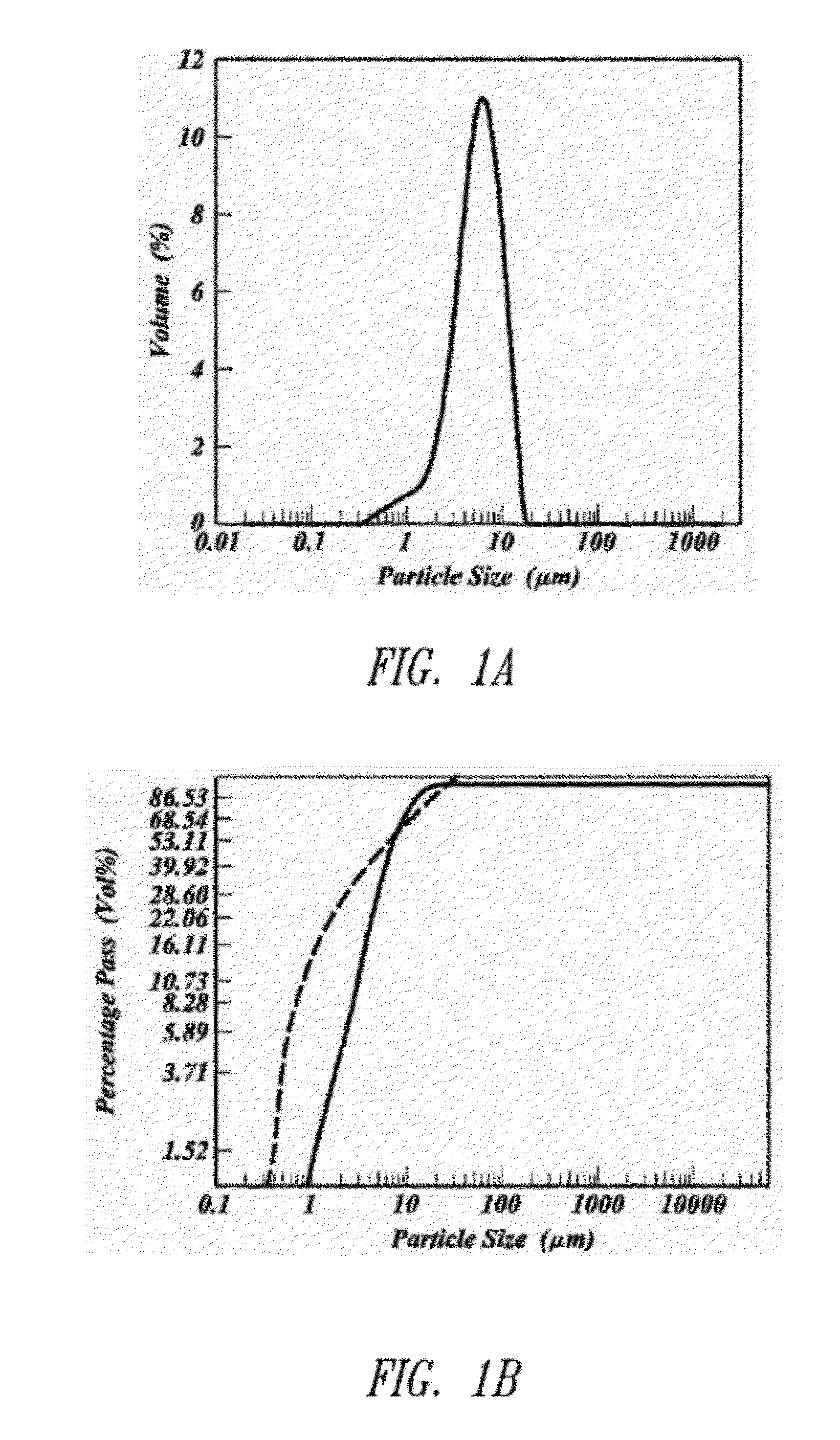
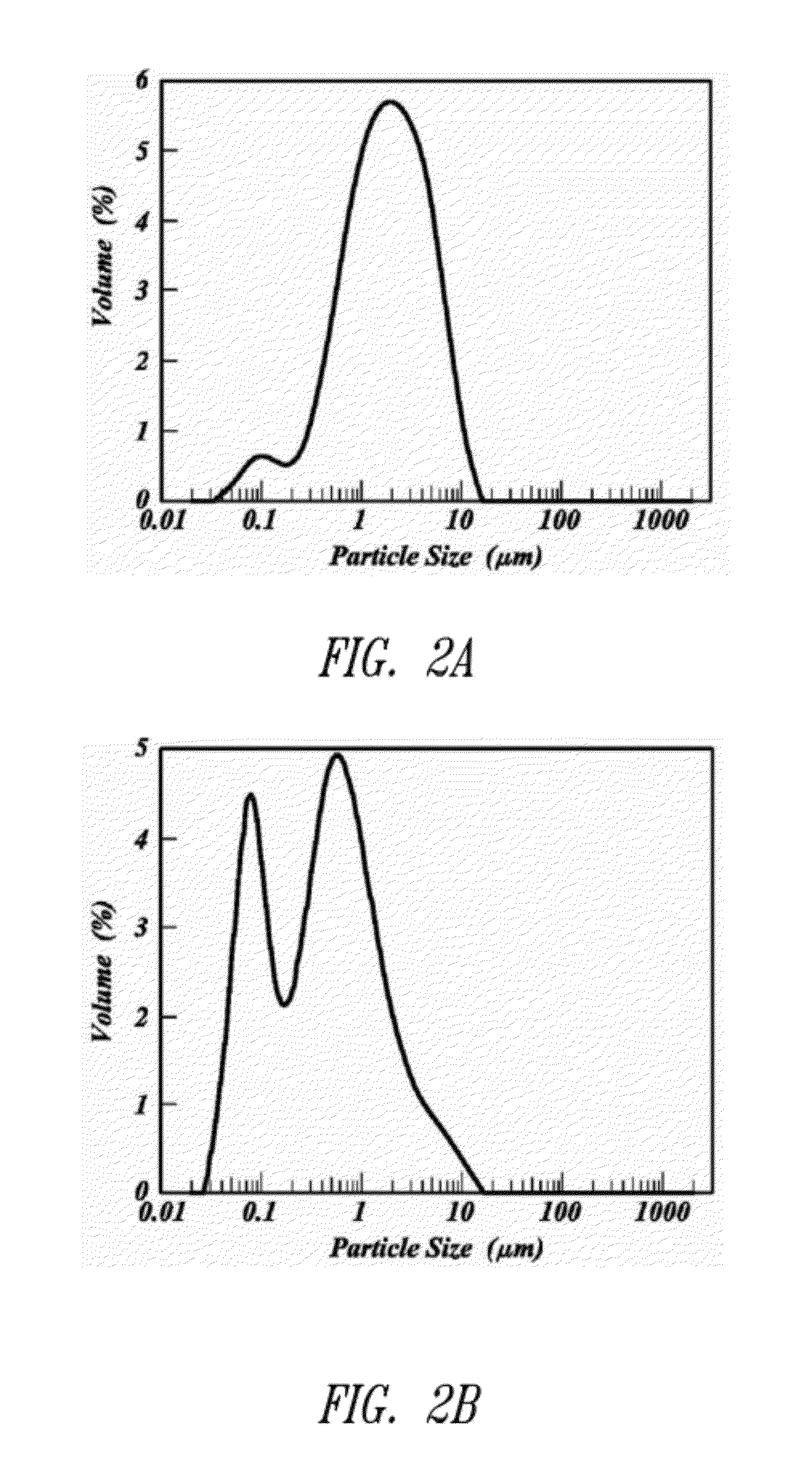
  • Enhanced packing of energy storage particles
  • Enhanced packing of energy storage particles
  • Enhanced packing of energy storage particles

Examples


example 1

Preparation of Polymer Gels

[0251]According to the methods disclosed herein, a polymer gel was prepared from a binary solvent system comprised of water and acetic acid (75:25), resorcinol, formaldehyde, and ammonium acetate. The material was then placed at elevated temperature to allow for gellation to create a polymer gel. Polymer gel particles were then created from the polymer gel and passed through a 4750 micron mesh sieve. The polymer gel particles were frozen by immersion in liquid nitrogen, loaded into a lyophilization tray at a loading of 3 to 7 g / in2 and lyophilized. The time to dry (as inferred from time for product to reach within 2° C. of shelf temperature) was related to the product loading on the lyophilizer shelf.

[0252]The surface area of the dried gel was examined by nitrogen surface analysis using a Micromeritics Surface Area and Porosity Analyzer (model TriStar II). The measured specific surface area using the BET approach was in the range of about 500 to 700 m2 / g.

example 2

Pyrolysis of Polymer Gels

[0253]Polymer gels prepared according to Example 1 were pyrolyzed via incubation at 900° C. in a nitrogen atmosphere for a dwell time of 60 min. The weight loss upon pyrolysis was 53±3%. In general, the specific surface area of the pyrolyzed gel was similar to that for the dried polymer gel before pyrolysis.

example 3

Preparation of Activated Carbon Samples

[0254]Activated carbon samples were prepared from the pyrolyzed samples prepared according to Example 2. The pyrolyzed carbon samples were activated by multiple passes through a rotary kiln (alumina tube with 2.75 in inner diameter) at 900° C. under a CO2 flow rate of 30 L / min, resulting in a total weight loss of about 45%.

[0255]The surface area of the activated carbon was examined by nitrogen surface analysis using a surface area and porosity analyzer. The measured specific surface area using the BET approach was in the range of about 1600 to 2000 m2 / g.


PUM

PropertyMeasurementUnit
Lengthaaaaaaaaaa
Lengthaaaaaaaaaa
Lengthaaaaaaaaaa

Abstract

The present application is generally directed to energy storage materials such as activated carbon comprising enhanced particle packing properties and devices containing the same. The energy storage materials find utility in any number of devices, for example, in electric double layer capacitance devices and batteries. Methods for making the energy storage materials are also disclosed.

Description

CROSS-REFERENCE TO RELATED APPLICATION[0001]The present application claims the benefit under 35 U.S.C. §119(e) of U.S. Provisional Patent Application No. 61 / 388,388 filed on Sep. 30, 2010; which application is incorporated herein by reference in its entirety.BACKGROUND[0002]1. Technical Field[0003]The present invention generally relates to the packing of energy storage particles, for example activated carbon particles, as well as to compositions and devices containing such particles and methods related to the same.[0004]2. Description of the Related Art[0005]Energy storage materials are commonly employed in electrical storage and distribution devices. For example, devices containing particles of activated carbon, silicon, sulfur, lithium, and combinations thereof, as energy storage media are ubiquitous throughout the electrical industry. Of these, activated carbon particles find particular use in a number of devices because the high surface area, conductivity and porosity of activat...

Claims


Application Information

Patent Timeline
IPC IPC(8): H01G9/155B32B5/16C01B31/08C01B31/00H01B1/04
CPCH01B1/04Y10T428/2982Y02T10/7022Y02E60/13H01M4/386H01M4/364H01M10/0569H01G2009/0007H01G11/60H01G11/32H01G9/042H01G2009/0025H01G9/035H01M4/583H01G11/34H01G11/38H01G11/62H01G11/24H01G11/30H01G11/42Y02E60/10Y02T10/70H01G9/145H01G11/00H01M4/587H01M10/0525H01M2004/021
Inventor COSTANTINO, HENRY R.GOODWIN, CHADSCOTT, WILLIAM D.FEAVER, AARON M.
Owner BASF AG
Learn More