Thermoelectric generators incorporating phase-change materials for waste heat recovery from engine exhaust

a technology of phase-change materials and generators, which is applied in the direction of thermoelectric devices, machines/engines, mechanical equipment, etc., can solve the problems of oxidizing, decomposing or otherwise degrading of thermoelectric elements, and achieve the effect of efficient extraction of energy

Active Publication Date: 2012-03-29
GM GLOBAL TECH OPERATIONS LLC
View PDF3 Cites 75 Cited by
  • Summary
  • Abstract
  • Description
  • Claims
  • Application Information

AI Technical Summary

Benefits of technology

[0007]Thermoelectric compositions are selected for effective operation at a temperature (or narrow temperature range) within typical expected upper levels of exhaust gas temperatures for a vehicle engine-exhaust system. In embodiments of this invention, one or more volumes of phase-change material are placed co-extensively between the hot exhaust gas and the high temperature side of thermoelectric modules. The composition of the phase-change material is selected to undergo melting and solidification cycles at the desired high-temperature side of the thermoelectric elements. Thus, the amount of phase-change material, its melting temperature, and its specific latent heat serve as a stabilizing temperature moderator for heat transfer between the thermoelectric material and the often continually-varying temperature of the exhaust gas. Similarly, a lower temperature phase-change material may be used between the low temperature side of the thermoelectric material and a medium used in heat exchange with the designated low temperature side of the thermoelectric module. Depending on the length of the thermoelectric device along the exhaust path and the typical temperature drop of the exhaust gas within such length, additional different phase-change materials and thermoelectric materials may be used in the hot and cold sides of down-stream modules. These downstream modules may be adapted for more efficiently extracting energy from the lower, downstream temperature engine exhaust.

Problems solved by technology

If a thermoelectric module overheats and exceeds its preferred operating temperature the thermoelectric elements might be oxidized or decompose or otherwise degrade.

Method used


Image

  • Thermoelectric generators incorporating phase-change materials for waste heat recovery from engine exhaust
  • Thermoelectric generators incorporating phase-change materials for waste heat recovery from engine exhaust
  • Thermoelectric generators incorporating phase-change materials for waste heat recovery from engine exhaust

Examples


Embodiment Construction

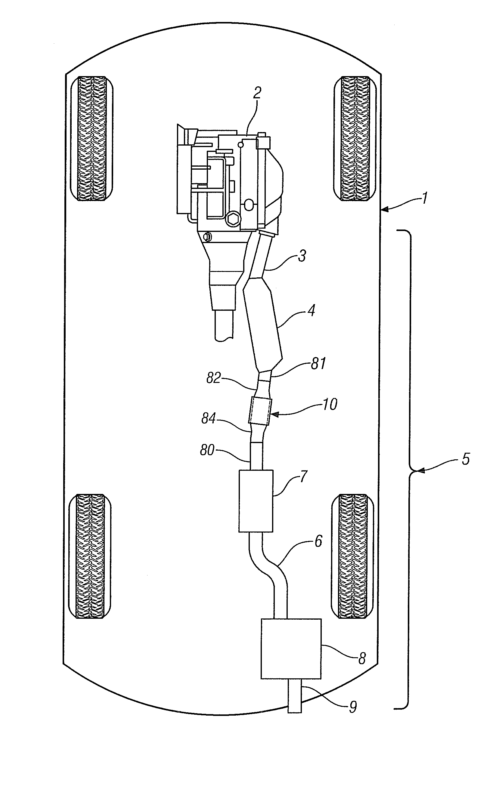
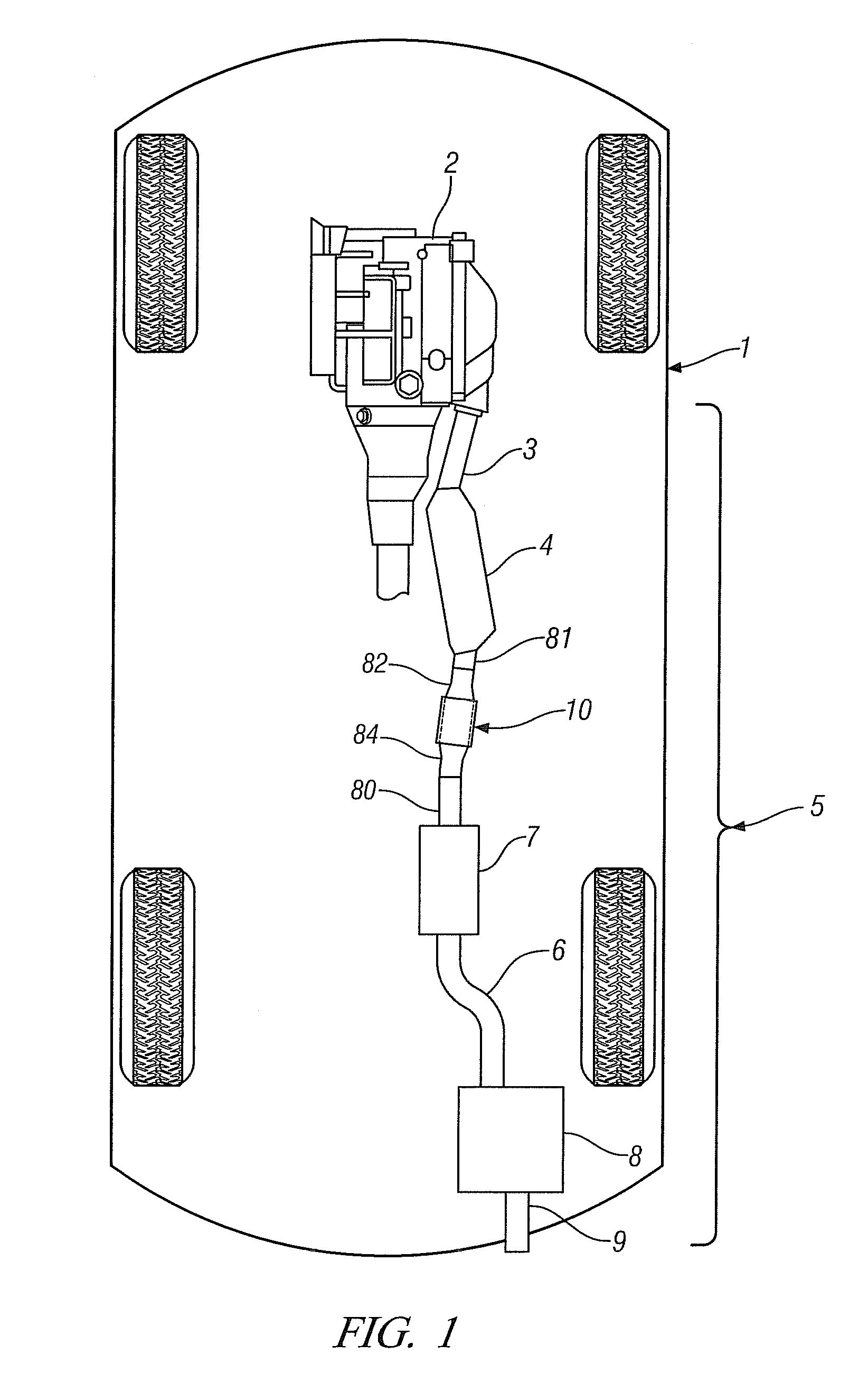
[0022]FIG. 1 shows, in plan view cutaway, the engine 2 and exhaust system 5 of an automobile 1 as well as a portion of the drive-train by which the engine power is delivered to the rear wheels to propel the vehicle. The exhaust system may comprise major elements and devices such as a catalytic convertor 4, a resonator 7, a muffler 8 and a tailpipe 9 each adapted for passage of exhaust from engine 2 and each serially interconnected by a plurality of hollow pipes or pipe segments identified as 3, 81, 82, 84, 80 and 6. Also shown in exhaust system 5 is a thermoelectric device 10, adapted for extraction of electrical energy from the thermal energy of the engine exhaust stream.

[0023]To enhance catalytic activity on cold engine start, catalytic convertor 4 is preferably positioned as close to the engine as possible. Thermoelectric device 10 is then preferably positioned downstream of but close to, catalytic convertor 6 where the exhaust gas is hottest. This will generally result in the th...


PUM


Abstract

Thermoelectric devices, intended for placement in the exhaust of a hydrocarbon fuelled combustion device and particularly suited for use in the exhaust gas stream of an internal combustion engine propelling a vehicle, are described. Exhaust gas passing through the device is in thermal communication with one side of a thermoelectric module while the other side of the thermoelectric module is in thermal communication with a lower temperature environment. The heat extracted from the exhaust gasses is converted to electrical energy by the thermoelectric module. The performance of the generator is enhanced by thermally coupling the hot and cold junctions of the thermoelectric modules to phase-change materials which transform at a temperature compatible with the preferred operating temperatures of the thermoelectric modules. In a second embodiment, a plurality of thermoelectric modules, each with a preferred operating temperature and each with a uniquely-matched phase-change material may be used to compensate for the progressive lowering of the exhaust gas temperature as it traverses the length of the exhaust pipe.

Description

[0001]This invention was made with U.S. Government support under Agreement No. DEAC050000R22725 awarded by the Department of Energy. The U.S. Government may have certain rights in this invention.TECHNICAL FIELD[0002]This invention pertains to devices and methods for efficiently extracting at least a portion of the thermal energy in an internal combustion engine exhaust stream and converting the extracted energy to electrical energy.BACKGROUND OF THE INVENTION[0003]Advances in the efficiency of both spark-ignition and compression-ignition internal combustion engines have contributed significantly to improved fuel economy of vehicles. Despite these improvements in engine efficiency an appreciable fraction of the available energy in the fuel is discharged as waste heat, a sizeable portion of which is discharged at high temperature in the vehicle exhaust.[0004]Yet further increases in vehicle fuel economy could be achieved if at least a portion of the waste heat contained in the exhaust...

Claims


Application Information

Patent Timeline
Patent Type & Authority Applications(United States)
IPC IPC(8): F01N5/02H01L35/30
CPCH01L35/30F01N5/025F01N2410/02H10N10/13
Inventor MEISNER, GREGORY P.YANG, JIHUI
Owner GM GLOBAL TECH OPERATIONS LLC
Why Eureka
Try Eureka