
Hemodialysis system and method

a technology of hemodialysis and flow path, which is applied in the field of hemodialysis systems and methods with blood flow paths, can solve the problems of increasing blood velocity and turbulence, high morbidity and mortality of dialysis patients, and imposing enormous costs on patients, so as to reduce endothelial cell damage, reduce circulating cell damage, and reduce the velocity and turbulence of blood flow

Inactive Publication Date: 2012-03-15
ZARATE ALFREDO R
View PDF7 Cites 41 Cited by
  • Summary
  • Abstract
  • Description
  • Claims
  • Application Information

AI Technical Summary

Benefits of technology

[0078]The dialysis blood circuit has been re-designed to decrease the velocity, turbulence and damage to circulating blood cells. Advantageously, such decreased damage to circulating blood cells in turn allows the realization of decreased incidence of medical complications and mortality caused by inflammation and oxidative stress, and concomitantly a decreased cost of care of dialysis patients.
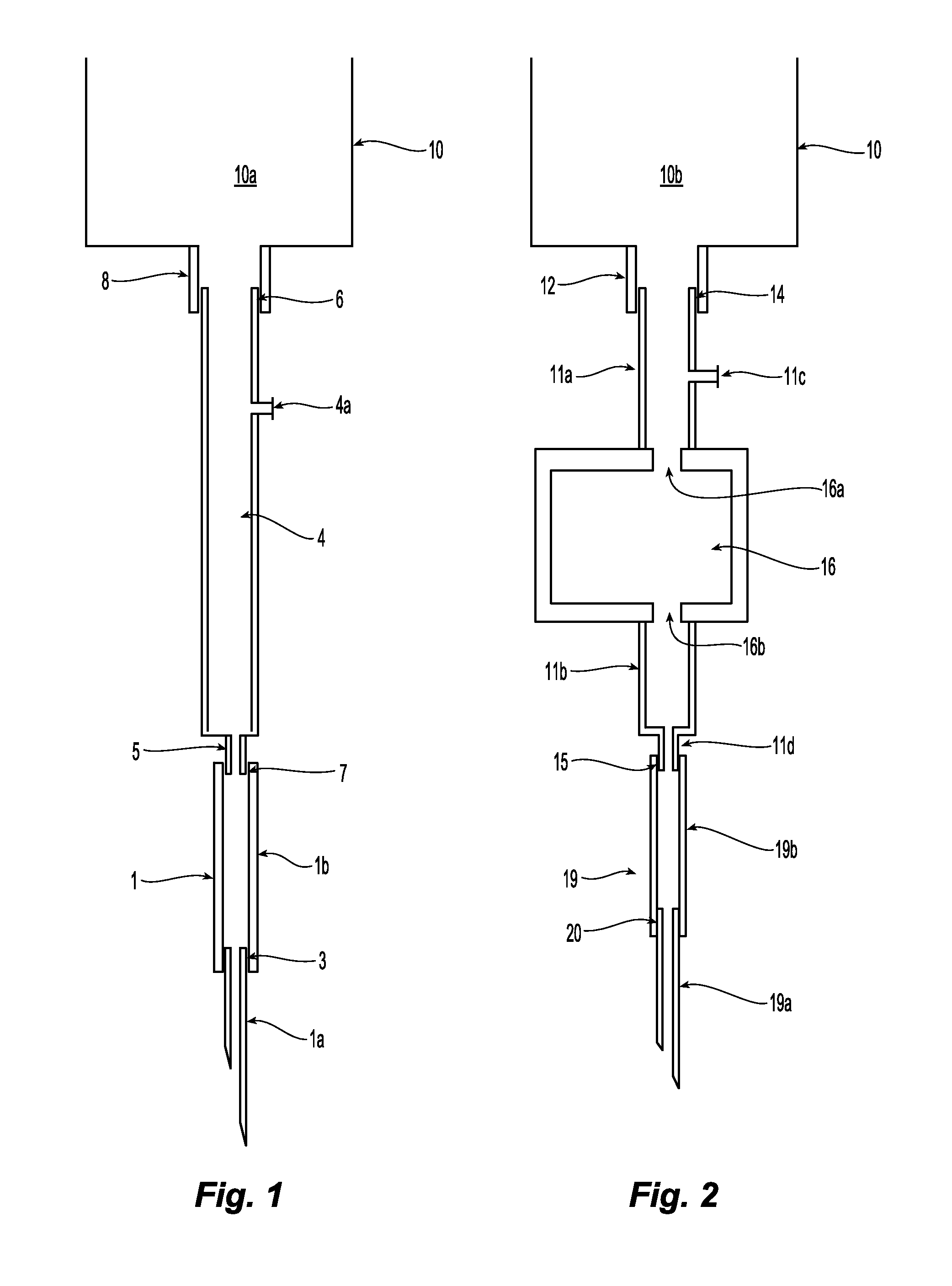
[0079]In the circuit disclosed herein, the geometry of the current circuit has been changed to decrease the velocity, shear stress and turbulence of the blood flow. The velocity of the blood in some segments of the circuit is decreased by changing the shape or the internal diameter of several segments of the dialysis circuit and the turbulence is decreased by decreasing the velocity of the blood, eliminating irregularities protruding into the lumen of the circuit, and / or rounding corners or transitions of the circuit.
[0087]An exemplary method of flowing blood through a dialysis catheter may include reducing circulating cell damage by decreasing the velocity and turbulence of the flow.
[0088]Another exemplary method of flowing blood through a dialysis catheter may include reducing endothelial cell damage by decreasing the velocity and turbulence of the flow.
[0089]Yet another exemplary method of flowing blood through a dialysis catheter may include reducing velocity and turbulence.

Problems solved by technology

The medical complications (morbidity) experienced and the cost imposed by these patients is enormous.
Blood circulates during dialysis through some segments of the currently-used dialysis blood circuit at extremely high velocity and turbulence, and this causes the activation of mononuclear cells, along with the generation and release of proinflammatory cytokines and oxidants that have been identified as causing high morbidity and mortality of dialysis patients.
Such connectors can substantially contribute to increases in blood velocity and turbulence in the hemodialysis circuit.
Moreover, the excessive length of the blood circuit increases the surface where circulating cells contact and are activated.
In addition, unlike the endothelium, the circulating cells experience friction against the wall of the circuit.
The circulation of blood through dialysis catheters may be more harmful than the circulation through dialysis needles for several reasons.
Second, blood exits the venous end of a dialysis catheter at extremely high velocity and turbulence.
The high velocity and turbulence of the blood inside the current dialysis circuit cause activation or destruction of circulating blood cells.
Because hemodialysis is given every other day to patients with permanent kidney failure, and the inflammatory and oxidative stress that is caused by dialysis lasts for several hours, the repetitive damage to cells during each dialysis could lead to a state of chronic (permanent) inflammation and oxidative stress and high morbidity and mortality.
In addition, excessive activation of platelets and repetitive damage to the endothelium of the vein can cause thrombus formation or stenosis of the vein.
The current design of the dialysis blood circuit does not fulfill the needs of hemodialysis as delivered to patients with permanent kidney failure at present.
But, in the current dialysis circuit, blood circulates at high velocity and turbulence, is exposed to walls of the circuit that are made of materials not resembling the endothelium of vessels, and the circuit is about 18 feet long, all of which are factors that can contribute to damage to circulating mononuclears.
Turbulent flow (and turbulent shear stress) is more harmful than laminar flow because the velocity of the blood is higher (there is more friction) and because of the chaotic motion of blood.
The cells inside the vortices and eddies impact on each other or on the walls of the circuit, causing greater activation or damage to the cells.
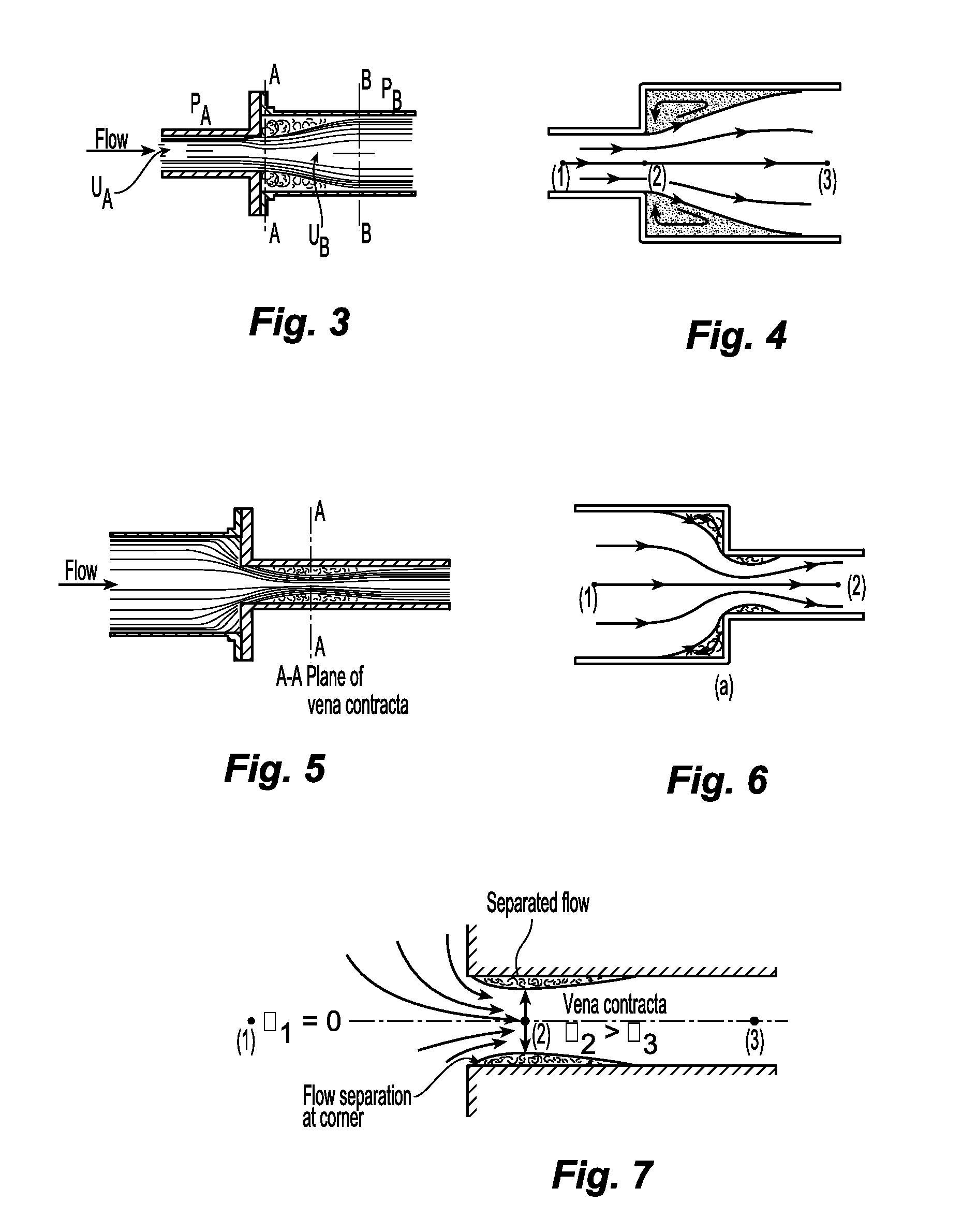
Any increase in the diameter of the circuit (deceleration of the flow), decreases in the diameter of the circuit (acceleration of the flow), bends, and sharp corners cause flow separation from the wall and can be damaging to circulating cells.
The vortices of flow separation cause chaotic movement of circulating cells and impact of cells on the wall.
Also, there is turbulence because the plasma would slow down before the cells in circulation and the cells up front would decelerate before the cells behind so that these cells would impact on each other.
Likewise, bends in the circuit can cause flow separation.
Cells are damaged by the high friction caused by the high velocity and turbulence.
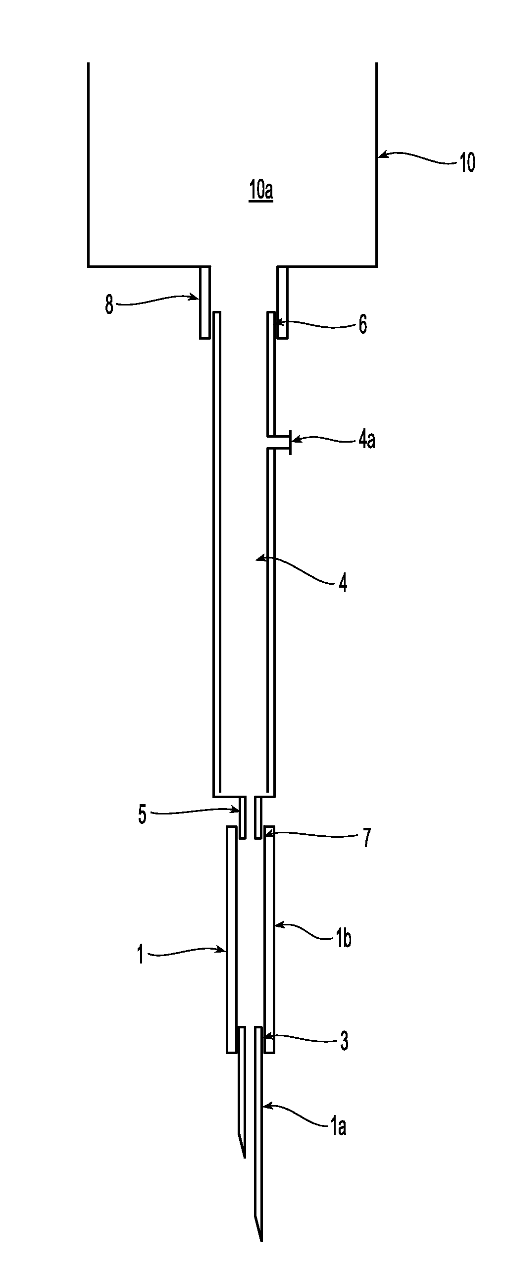
Also, cells coming from fistula needle tubing 1b are damaged when they impact on the rim of the connector 5.
Impact with the rim can cause damage to many circulating cells: in one existing product, the external diameter of the connector is 3 mm and the internal diameter is 2 mm.
That is, about 25% of the blood cells flowing through the cross-section could impact on the rim and get damaged.
In addition, circulating cells can be damaged by impacting on the rim of the metal cannula.
Turning to FIG. 8, a rotating blood pump 30 also can be a major cause of high pressure, velocity and turbulence with associated activation or destruction of circulating cells.
Each time the roller progressively compresses the tube, the diameter of the tubing decreases, the velocity of the blood inside the tubing increases, and turbulence is caused by the change in internal diameter and change in velocity.
Therefore, much kinetic energy is wasted in turbulent flow.
High shear stress is the cause of the minimal hemolysis associated with standard dialysis and the cause of serious hemolysis reported in the literature.
During dialysis, turbulent flow of high velocity is present inside the vascular access in the area past the venous needle and this turbulent flow (and turbulent shear stress) is harmful to the endothelial and circulating blood cells because the cells experience friction with each other and impact on each other or on the wall of the vascular access causing more significant activation or destruction of cells.
Turbulent flow does not occur in normal vessels because it is an inefficient way to transfer fluids (⅓ higher consumption of energy than laminar flow), it would require much higher arterial pressure to propel blood in normal vessels, and turbulent flow, unlike laminar flow, is harmful to cells.
Therefore, much kinetic energy is wasted in turbulent flow; if the blood flow in humans would be turbulent, higher arterial pressure would be necessary to perfuse distant organs.
Very high turbulence and wall shear stress cause erosion, denudation or necrosis of the endothelium, and lysis of circulating cells.
There are consequences to the damage to the endothelium and the release of cytokines and oxidants of cells.
In particular, the damage to the endothelium and to circulating cells caused by the high velocity and turbulence of the flow past the venous needle during dialysis can cause or contribute to cause several complications in dialysis patients.
First, there can be vascular access complications.
The high turbulence of the flow causes endothelial damage.
Repetitive endothelial damage in the same site of the vascular access during four hours of dialysis every other day can lead to stenosis and thrombosis of the vascular access.
Access complications, principally stenosis and thrombosis, are the major cause of morbidity of hemodialysis patients, they consume >10% of the total cost of care of all the dialysis patients, and the occurrence of access complications is reaching epidemic proportions.
Also, failure of dialysis fistulas and grafts leads to the use of dialysis catheters that cause frequent infections, chronic inflammation and even death.
Oxidants stimulate the release of proinflammatory cytokines and ET-1, promote adhesion of circulating cells to the endothelium and the activation of cells, and cause multiple cells dysfunctions.
Those studies demonstrated, for example, that blood circulates in some segments of the current dialysis circuit at velocities up 100 times higher than the velocity of blood in peripheral veins, thus causing extremely high turbulence.
These lateral openings do not allow the exit of blood unless the pressure at the distal end is increased by occlusion against the wall or clots because, as mentioned above, blood running at high velocity does not take sharp corners.

Method used


Image

  • Hemodialysis system and method
  • Hemodialysis system and method
  • Hemodialysis system and method

Examples


Embodiment Construction

[0144]Material for the venous blood line. The ideal circuit should be manufactured with an elastic material that will allow expansion during the compression cycle and spontaneous contraction to regain initial diameter during the decompressing cycle.

[0145]A variety of connections between components of the dialysis circuit are contemplated to permit lower velocity and turbulence therein.

[0146]Connection between metal cannula and fistula needle tubing. In one embodiment, shown in FIG. 10, a free end of metal cannula 50 has a rim 50a that is “hidden” by plastic fistula needle tubing 52 proximate a free end thereof so that rim 50a does nor protrude into the lumen of tubing 52.

[0147]In another embodiment, shown in FIG. 11, a free end of metal cannula 60 has a tapered rim 60a such that the rim does not abruptly cause a change in diameter of the flow path when cannula 60 is connected with fistula needle tubing 62, but instead there is a gradual change in diameter.

[0148]Such designs of FIGS....


PUM


Abstract

Hemodialysis systems and methods with streamlined blood flow paths are provided. Such streamlined blood flow paths facilitate flow without undue damage to circulating cells.

Description

CROSS-REFERENCE TO RELATED APPLICATIONS[0001]The benefits of U.S. Provisional Application No. 61 / 350,911 filed Jun. 2, 2010 and entitled “Hemodialysis System and Method” and U.S. Provisional Application No. 61 / 376,679 filed Aug. 25, 2010 and entitled “Hemodialysis System and Method” are claimed under 35 U.S.C. §119(e), and the entire contents of these applications are expressly incorporated herein by reference thereto.FIELD OF THE INVENTION[0002]Hemodialysis systems and methods are disclosed. More particularly, hemodialysis systems and methods with blood flow paths that avoid flow turbulence are disclosed, including the use of needles and / or catheters.BACKGROUND OF THE INVENTION[0003]Currently there are about 400,000 end-stage renal disease (ESRD) patients on dialysis in the United States and about 1,600,000 world-wide, and their number is expected to grow exponentially. The medical complications (morbidity) experienced and the cost imposed by these patients is enormous. Most of the...

Claims


Application Information

Patent Timeline
Patent Type & Authority Applications(United States)
IPC IPC(8): A61M1/14
CPCA61M1/16A61M1/3653A61M2206/11A61M39/10A61M1/367A61M1/3655A61M1/3659A61M1/3661
Inventor ZARATE, ALFREDO R.
Owner ZARATE ALFREDO R
Learn More