Radio-Frequency Power Amplifier with Fast Envelope Tracking

a power amplifier and envelope tracking technology, applied in the direction of amplifiers, amplifiers with semiconductor devices only, amplifiers with semiconductor devices, etc., can solve the problem of not being able to use commercially available diodes, and achieve the effect of reducing the bandwidth of the envelope signal

Active Publication Date: 2012-03-15
EUROPEAN SPACE AGENCY
View PDF3 Cites 38 Cited by
  • Summary
  • Abstract
  • Description
  • Claims
  • Application Information

AI Technical Summary

Benefits of technology

[0012]According to the invention, this aim is achieved by a RF power amplifier wherein envelope tracking is provided by a fast DC / DC converter using two RF power transistors for implementing both the switching element and the rectifier of said DC / DC converter. Advantageously, these two transistors are of a same technology, which can preferably be the same as that of the transistor used for amplifying the RF signal. Unexpectedly, a RF power transistor connected as a rectifier allow achieving a high commutation speed (several MHz) while dealing with comparatively high currents (1A or more) and powers (several Watts), which is not possible using commercially available diodes. Thus, the use of a transistor connected as a two-terminal device allows avoiding the “diode bottleneck” discussed in reference with prior art document US 2008 / 111631.
[0019]Monolithic integration is clearly facilitated by the use of active device (amplifying transistor, switch and rectifier) of a same technology. Moreover, this also allows a particularly compact assembly, minimizing parasitic component, in case a discrete implementation is preferred.
[0024]A radio-frequency power amplifier according to any of the preceding claims can further comprise a driving circuit for driving said switching device with a PWM signal representative of an envelope of the RF signal to be amplified. A low-pass filter can be provided for reducing the bandwidth of the envelope signal on which the PWM signal driving the DC / DC converter depends.

Problems solved by technology

Unexpectedly, a RF power transistor connected as a rectifier allow achieving a high commutation speed (several MHz) while dealing with comparatively high currents (1A or more) and powers (several Watts), which is not possible using commercially available diodes.

Method used


Image

  • Radio-Frequency Power Amplifier with Fast Envelope Tracking
  • Radio-Frequency Power Amplifier with Fast Envelope Tracking
  • Radio-Frequency Power Amplifier with Fast Envelope Tracking

Examples


first embodiment

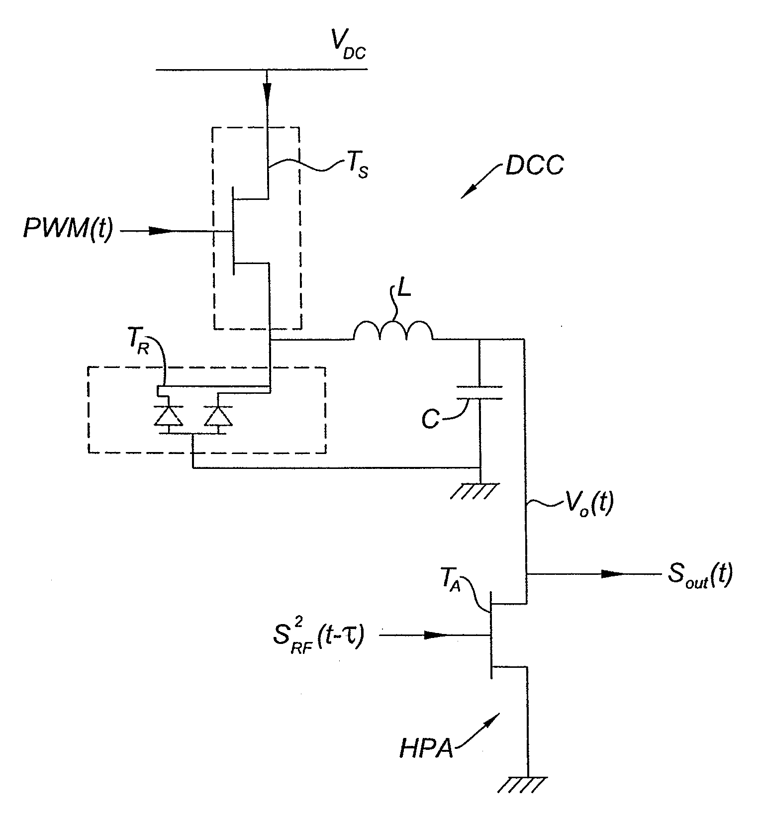
[0037]FIG. 3 shows the circuit diagram of a portion of a RF power amplifier with envelope tracking according to the invention. More precisely, FIG. 3 only represents the DC / DC converter switching cell, of the “buck” type, comprising:[0038]a switching transistor TS, whose drain is connected to a main power supply VDC and whose gate is fed by a pulse-width modulation PWM(t) representative of the envelope E(t);[0039]a “rectifying transistor” TR, whose drain and source are connected together to the source of the switching transistor, while the gate is connected to the ground; the transistor connected this way operates as a free-wheeling diode whose anode is formed by the gate and the whose cathode is formed by the drain and source;[0040]An inductor L and a capacitor C are connected to the source of the switching transistor TS, forming an LC low-pass filter;[0041]The DC signal V0(t) whose value (lower or equal to VDC) is proportional to E(t)—with a certain time delayτ—is applied to the d...

second embodiment

[0050]FIG. 5 shows the circuit diagram of a portion of a RF power amplifier with envelope tracking according to the invention. More precisely, FIG. 5 only represents the switching cell of a “boost” DC / DC converter, comprising:[0051]a switching transistor TS, whose drain is connected to a main power supply VDC through inductor L, and whose gate is fed by pulse-width modulation PWM(t);[0052]a “rectifying transistor” TR, whose gate is connected to the drain of the switching transistor, while the drain and source are connected together to capacitor C, which in turn is connected to the source of TS and the ground. The transistor TR connected this way operates as a free-wheeling diode whose anode is formed by the gate and the whose cathode is formed by the drain and source;[0053]The DC signal V0(t)—higher or equal to VDC—is applied to the drain of the amplifying transistor TA which operates in common-source configuration and constitutes the hearth of the high-power amplifier HPA. The dela...


PUM


Abstract

A radio-frequency power amplifier with envelope tracking, comprising: a power RF amplifying device for amplifying a RF signal; and a switching DC / DC converter, comprising a switching device and a rectifying device, for providing said power RF amplifying device with a DC power supply at a voltage level proportional to an envelope of said RF signal; wherein said switching device is a RF power transistor; characterized in that said rectifying device, and preferably also said power RF amplifying device, is also a transistor of a same technology, connected as a two-terminal device. Preferably, said power RF amplifying device is also a transistor of said same technology. A low-pass filter can also be provided for reducing the bandwidth of the envelope signal on which the PWM signal driving the DC / DC converter depends.

Description

FIELD OF THE INVENTION[0001]The invention relates to a radio-frequency power amplifier with envelope tracking, in particular for use in space telecommunications and / or cellular networks.BACKGROUND[0002]Improving the efficiency, consumption, dissipation and / or linearity of radio-frequency (RF) solid state power amplifiers is a high priority for manufacturers of ground mobile telephony network infrastructures due to the very demanding requirements for 3G-UMTS. The very high linearity required dramatically impacts the efficiency of power amplifiers used in base-stations. Similar requirements arise in space applications.[0003]It is well-known; however, that linearity and energetic efficiency are somehow contradictory requirements.[0004]The “flexible amplifier” concept consists in adjusting the power supply to the average RF power in order to achieve both high linearity and high efficiency. “Envelope tracking” is an evolution of this approach, wherein the power supply is adjusted in a dy...

Claims


Application Information

Patent Timeline
Patent Type & Authority Applications(United States)
IPC IPC(8): H03F3/21
CPCH03F1/0227H03F3/195H03F1/0222H03F2200/102H03F2200/504H03F3/245
Inventor LE GALLOU, NICOLASDELEPAUT, CHRISTOPHESARDIN, DAVIDCAMPOVECCHIO, MICHEL
Owner EUROPEAN SPACE AGENCY
Why Eureka
Try Eureka