
Blood Chamber for an Optical Blood Monitoring System

a blood chamber and optical technology, applied in the field of optical blood monitoring systems, can solve the problems that the signal processing techniques do not adequately account for the effects of ambient light, and achieve the effect of facilitating the accurate measurement of oxygen saturation levels

Active Publication Date: 2012-03-08
FRESENIUS MEDICAL CARE HLDG INC
View PDF18 Cites 38 Cited by
  • Summary
  • Abstract
  • Description
  • Claims
  • Application Information

AI Technical Summary

Benefits of technology

[0012]A primary objective of the invention is to facilitate the accurate measurement of oxygen saturation levels over the full expected dynamic range of the detected signals used to calculate oxygen saturation levels via a ratiometric model, and to do so at both high and low hematocrit levels.
[0013]The invention pertains to a blood chamber having a chamber body that is made at least partially of a material that is opaque to red light having the same wavelength as one of the wavelengths used in a ratiometric model to calculate oxygen saturation levels of blood flowing through the blood chamber. For this purpose, a blue-tinted chamber body may be used to attenuate the red light ducting through the chamber body and isolate the lenses from the ducted light, thereby avoiding inaccuracies in the measurement of oxygen saturation levels that can accompany the measurement of low levels of oxygen saturation when the patient has a low hematocrit value.

Problems solved by technology

Some signal processing techniques do not adequately account for the effects of ambient light, and in these applications the moat is most likely critical to attenuate infrared light at about 810 nm and 1300 nm even if the chamber body is blue-tinted to attenuate visible 660 nm red light.

Method used


Image

  • Blood Chamber for an Optical Blood Monitoring System
  • Blood Chamber for an Optical Blood Monitoring System
  • Blood Chamber for an Optical Blood Monitoring System

Examples


first embodiment

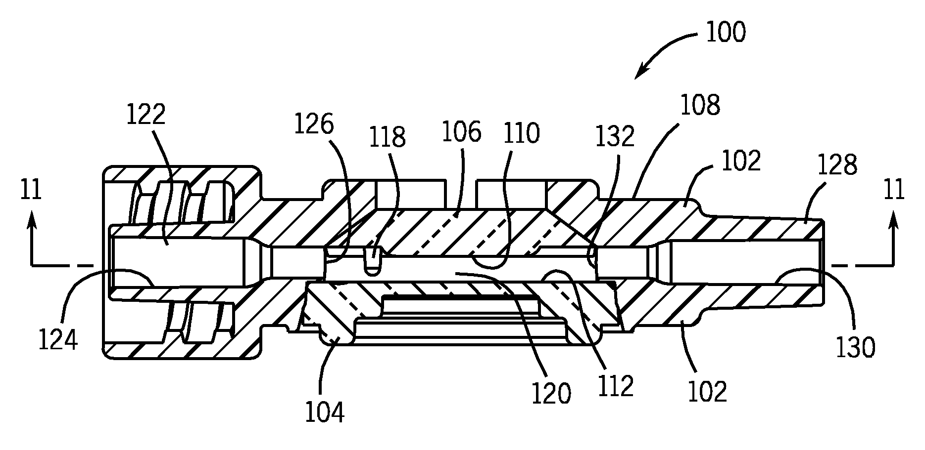
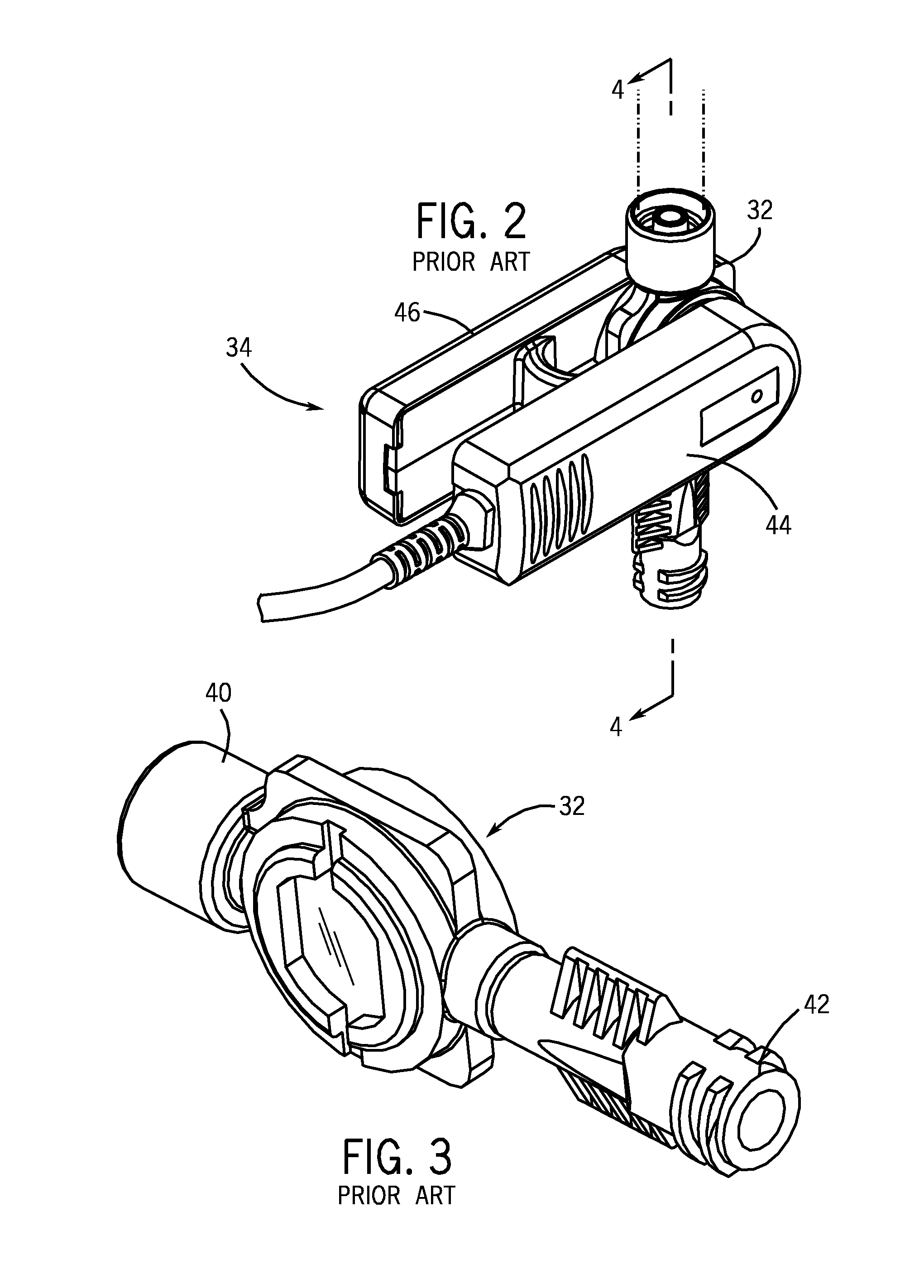
[0052]FIGS. 7 through 11 illustrate a blood chamber 100 in accordance with the invention. The blood chamber 100 is similar in many respects to the prior art blood chamber 32 shown in FIGS. 3 and 4; however, the blood chamber 100 has a chamber body 102 that includes a blue-tinted portion 108 in order to attenuate light ducting at the 660 nm wavelength. Referring in particular to FIG. 10, the lens 106 on the chamber body 102 is preferably made of clear, medical grade polycarbonate material which is molded with a polished finish in order to facilitate reliable light transmission, e.g. Bayer Makrolon FCR2458-55115 (no regrind allow), which is blood contact approved, USP XX11, Class V1. It is expected that the material be certified as to grade number, lot number and date of manufacture. No mold release should be used, and any lubrications should be food grade and not silicon based. The molded parts should be produced with no loose foreign material greater than 0.1 mm2 and no embedded for...

second embodiment

[0057]FIGS. 12 through 14 illustrate a blood chamber 200 constructed in accordance with the invention. Blood chamber 200 includes a moat 264 surrounding the internal blood flow cavity 220 as in the prior art blood flow chamber 32 illustrated in FIGS. 3 and 4. In fact, the structure and dimensions of the blood chamber 200 shown in FIGS. 12 through 14 are substantially the same as those shown in the prior art blood chamber 32, with the primary difference being that portion 208 of the blood chamber body 202 in FIGS. 12 through 14 is made of a blue-tinted material, such as dark blue tinted polycarbonate, in order to alternate ducted red light particularly at 660 nm if the LED emitter 88 emits red light at 660 nm. Because of the presence of the moat 264, ducting of the infrared radiation through the chamber body 202 (or ambient light) is even less likely to cause errors in the mathematics pertaining the ratiometric models for determining the real-time oxygen saturation and hematocrit lev...


PUM


Abstract

An extracorporeal blood chamber for an optical blood monitoring system includes an opaque chamber body in order to prevent inaccuracies when measuring oxygen saturation levels due to light ducting, which can occur at low oxygen saturation levels and low hematocrit levels. In one embodiment, the blood chamber need not include a moat as is present in conventional blood chambers.

Description

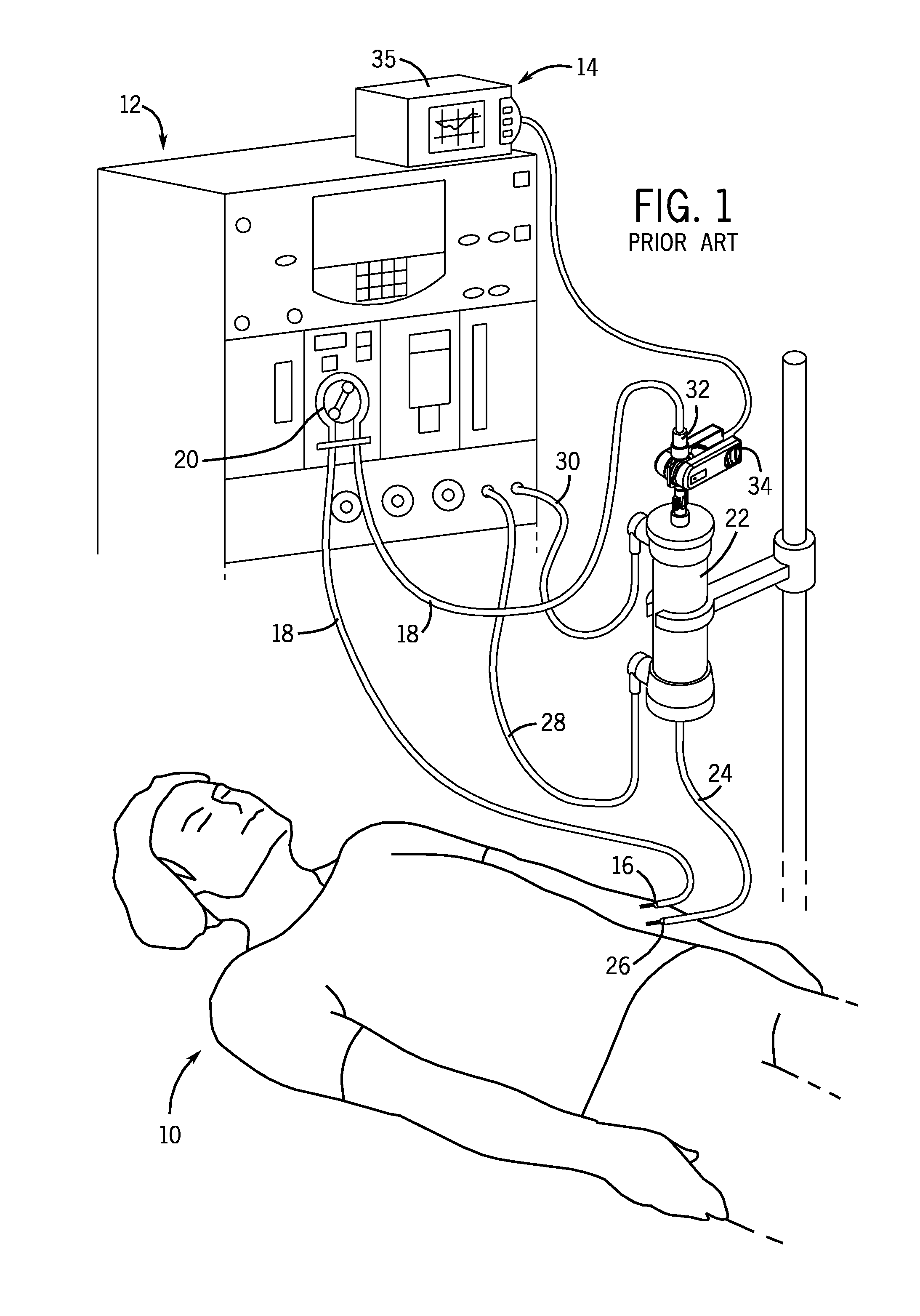
FIELD OF THE INVENTION[0001]The invention relates to optical blood monitoring systems, and in particular, single-use blood chambers for the real-time measurement of hematocrit, oxygen saturation levels and / or other blood constituents. The blood chambers are useful when monitoring extracorporeal patient blood flow. The invention is particularly directed to improving the reliability of low level oxygen saturation measurements.BACKGROUND[0002]The type of blood chambers to which the invention pertains have been widely used to monitor a patient's hematocrit and oxygen saturation levels during conventional hemodialysis treatments. Patients with kidney failure or partial kidney failure typically undergo hemodialysis treatment in order to remove toxins and excess fluids from their blood. To do this, blood is taken from a patient through an intake needle or catheter which draws blood from an artery located in a specifically accepted access location (for example, a shunt surgically placed in ...

Claims


Application Information

Patent Timeline
Patent Type & Authority Applications(United States)
IPC IPC(8): A61B6/00G01N21/3577
CPCA61B5/14557A61M2205/3313A61M2205/3306A61M1/367G01N21/314G01N21/05G01N21/3151G01N2021/3144G01N2021/3148G01N2021/058A61B2562/185A61B5/14535A61B5/1455A61B5/14552
Inventor BARRETT, LOUIS L.LAW, PERRY N.
Owner FRESENIUS MEDICAL CARE HLDG INC
Learn More