Eureka AIR delivers breakthrough ideas for toughest innovation challenges, trusted by R&D personnel around the world.

Method and System for Distributed Communication

a distributed communication and communication method technology, applied in the field of methods and systems for distributed communication, can solve the problems of reducing the sensitivity and performance of the system, limiting the optimal positioning and orientation, and no flexibility in changing the position, so as to improve the performance and improve the performan

Active Publication Date: 2012-03-08
GOLBA LLC
View PDF5 Cites 104 Cited by
  • Summary
  • Abstract
  • Description
  • Claims
  • Application Information

AI Technical Summary

Benefits of technology

[0004]This focus of this invention is an improved architecture where a centralized wireless communication system is divided into smaller components. These components are then distributed and placed at different locations for improved performance. The sub-components can support multiple communication mechanisms and standards and more than one sub-component can be used to improve performance.
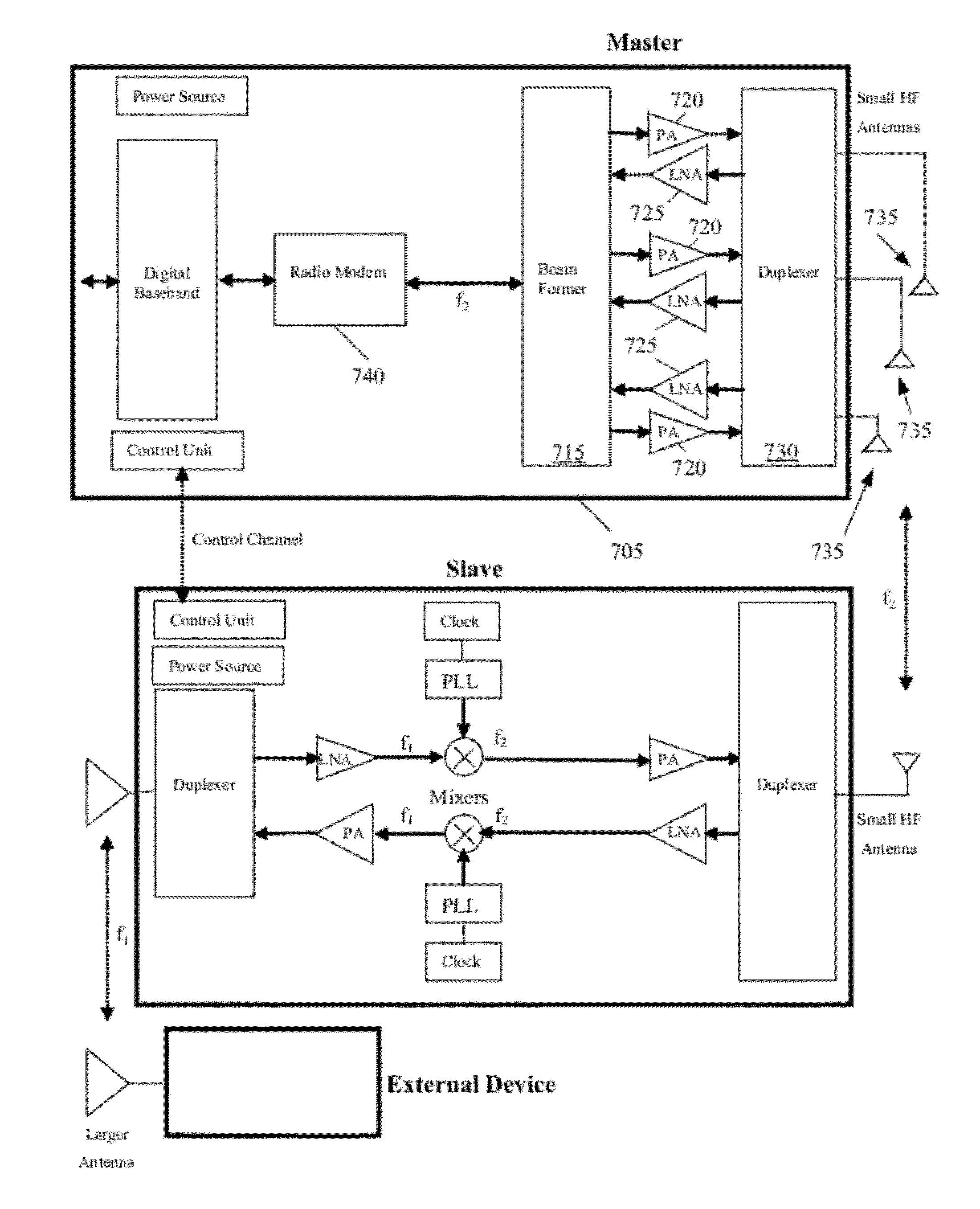
[0005]A decentralized communication device is provided that facilitates optimal positioning and orientation of one or more antennas for communicating with external devices. The decentralized communication device includes one or more master components and one or more slave components. The master and the slave components are physically separate and communicate wirelessly.
[0008]The radio modem also down converts received signals from the carrier frequency, performs analog to digital conversion and sends the information to the baseband module for processing. Placing the large antennas required to communicate with the external devices in the slave which is physically separate from the master, allows the slave antennas to be placed in more optimal locations and more optimal orientations to achieve improved sensitivity, performance, and diversity.
[0009]In some embodiments, one or more masters and one or more slaves are included in an electronic device such as a television (TV), a computer, a laptop, a gaming device, etc. to use the master to communicate wirelessly with external devices by using the slaves as intermediaries. In some of these embodiments, the master performs beam-forming by changing the radio frequency (RF) delays, phases and amplitudes for different slaves in order to maximize the signal received at the external device.
[0010]Some embodiments implement Multiple Input Multiple Output (MIMO) wireless communication between the master and slave and / or between the slave and the external devices to improve system performance. One advantage of this method is that by separating the front-end from the master, the multiple antennas of the slaves can be placed further apart and hence provide better antenna diversity since the antennas will experience different multipath and fading characteristics. The greater distance between the antennas of the slaves means less interference between the antennas. MIMO wireless systems use diversity coding to improve system performance. With diversity coding the signal is coded using space-time coding methods. These coding methods exploit the independent fading characteristics of the multiple antenna signal paths. MIMO systems also offer spatial multiplexing where a signal is divided into several lower rate streams and each stream is transmitted from a different transmit antenna in the same frequency channel. Spatial multiplexing increases channel capacity at higher signal to noise ratios (SNR).

Problems solved by technology

However, in a centralized communication device, the positions are fixed on an integrated chip or a circuit board and there is no flexibility in changing the position.
This limits the optimal positioning and orientation of the antenna, which in turn results in lower sensitivity and lower performance of the system.

Method used


Image

  • Method and System for Distributed Communication
  • Method and System for Distributed Communication
  • Method and System for Distributed Communication

Examples


Embodiment Construction

[0033]In the following detailed description of the invention, numerous details, examples, and embodiments of the invention are set forth and described. However, it will be clear and apparent to one skilled in the art that the invention is not limited to the embodiments set forth and that the invention may be practiced without some of the specific details and examples discussed.

[0034]A decentralized communication device is provided that facilitates optimal positioning and orientation of one or more antennas for communicating with external devices. The decentralized communication device includes one or more master components and one or more slave components. The master and the slave components are physically separate and communicate wirelessly.

[0035]The slave includes the antennas for communicating with external devices as well as a front-end for sending signals to and receiving signals from the antennas. In some embodiments, the front-end includes a time or frequency duplexer, one or...


PUM


Abstract

A decentralized communication device is provided that facilitates optimal positioning and orientation of one or more antennas for wireless communication with external devices. The decentralized communication device includes one or more master components and one or more slave components. The master and the slave components are physically separate and communicate wirelessly. In some embodiments the slave acts as a carrier frequency translator between the master and an external wireless device, where it communicates with the external device using a first frequency and communicates with the master using a second frequency which is different from the first frequency. In another embodiment the slave has most or all the physical layer to do the digital coding, digital modulation, data framing, data formatting and data packetization for communicating with an external device, in which case digital coding and digital modulation is distributed between the master and the slave.

Description

CLAIM OF BENEFIT TO PRIOR APPLICATIONS[0001]The present application claims the benefit of U.S. Provisional Patent Application 61 / 377,407, entitled, “Method and System for Distributed Communication System,” filed Aug. 26, 2010. The contents of U.S. Provisional application 61 / 377,407 are hereby incorporated by reference.BACKGROUND[0002]Centralized communication devices typically include baseband, radio modem, and radio front-end. The modem modulates and demodulates the carrier signals to encode and decode the transmitted and received information. The front-end includes a power amplifier to amplify the signal being transmitted, a low noise amplifier to amplify the received signals, a time or frequency duplexer, and an antenna to send and receive signals to / from external devices. In a centralized system, the radio modem and the radio front-end are physically close together. Often as a single integrated circuit chip or several chips fixed on circuit boards that cannot move against each o...

Claims


Application Information

Patent Timeline
Patent Type & Authority Applications(United States)
IPC IPC(8): H04B1/38H04L5/14
CPCH04B1/28H04W84/20H04B7/14H04B1/38H04B1/0064H04B1/0096H04L5/1461H04L27/0002
Inventor MOSHFEGHI, MEHRAN
Owner GOLBA LLC
Why Eureka
Eureka Blog
Learn More