
Golf Club Head

a golf club and head technology, applied in the field of golf club head, can solve the problems of insufficient ability, lack of effort and time to improve ability, and difficulty for professional or amateur golfers, and achieve the effects of improving the flying distance of the golf ball, improving the ability, and improving the elastic deformation ra

Inactive Publication Date: 2012-03-01
KOREA NUCLEAR ENG
View PDF35 Cites 15 Cited by
  • Summary
  • Abstract
  • Description
  • Claims
  • Application Information

AI Technical Summary

Benefits of technology

[0009]In order to solve the above problems, the present invention is directed to a golf club head including a variation part, which is easily flexible, formed at a striking surface of a head, and capable of increasing repulsive power caused by an elastic deformation rate of the striking surface upon striking a ball to improve a flying distance, and strengthening an elastic recovering force of corner parts formed by the variation part to further enhance stability in a ball-flying direction and a ball spin function.
[0014]According to the golf club head of the present invention, the variation part formed at the striking surface of the striking plate has a thickness smaller than that of the striking plate, upper and lower sides of the variation part are continuously formed with the striking plate, and a center part of the variation part is recessed from the striking surface to form a groove on the striking surface. Therefore, the variation part can be easily and elastically deformed upon striking a golf ball to increase an elastic deformation rate at which the striking surface of the striking plate is deformed inward, and thus, an elastic recovery force of the striking plate itself and an elastic recovery force of the variation part can also be increased to further improve a flying distance of the golf ball.
[0015]In addition, since a position of a center of gravity of the striking plate is far away from the striking surface by a gravity center extension projecting rearward from the striking plate, rotation moment of the gravity center extension is increased upon recovery of the elasticity of the striking surface, and thus, the increased rotation moment of the gravity center extension is applied to upper and lower corner parts of the groove, so that anti-slide of a golf ball, stability of a ball-flying direction and a spin function of a golf ball can be further improved.
[0016]As described above, the golf club head of the present invention helps people who enjoy golf for the purpose of interest or exercise or beginners who have insufficient abilities such as a basic swing posture, power and swing technique strengthen a recovering force upon strike so as to improve the flying distance. In addition, a function of the corner parts formed at the striking surface can be improved to increase stability of the ball-flying direction, and various swing techniques can be performed by the ball spin so that people can be more interested in golf and enjoy golf.

Problems solved by technology

Professional or amateur golfers are subjected to difficulties due to lack of adjustability related to the ball-flying direction, flying distance, ball spin, and so on, caused by differences in individual ability upon striking, and make steady efforts to improve such ability.
However, people who play golf for the purpose of interest or exercise have insufficient ability related to basic swing posture, power and striking technique, and a lack of effort and time to improve the ability.
For this reason, stability in ball-flying direction is decreased, a flying distance is insufficient, and various techniques such as straight driving, back spin, slicing, and so on, according to a level of ball spin, cannot be easily used.
As a result, due to lack of ability, some people cannot perform a desired swing to enjoy golf so that they lose interest in golf and consequently avoid playing golf.

Method used


Image

  • Golf Club Head
  • Golf Club Head
  • Golf Club Head

Examples


first embodiment

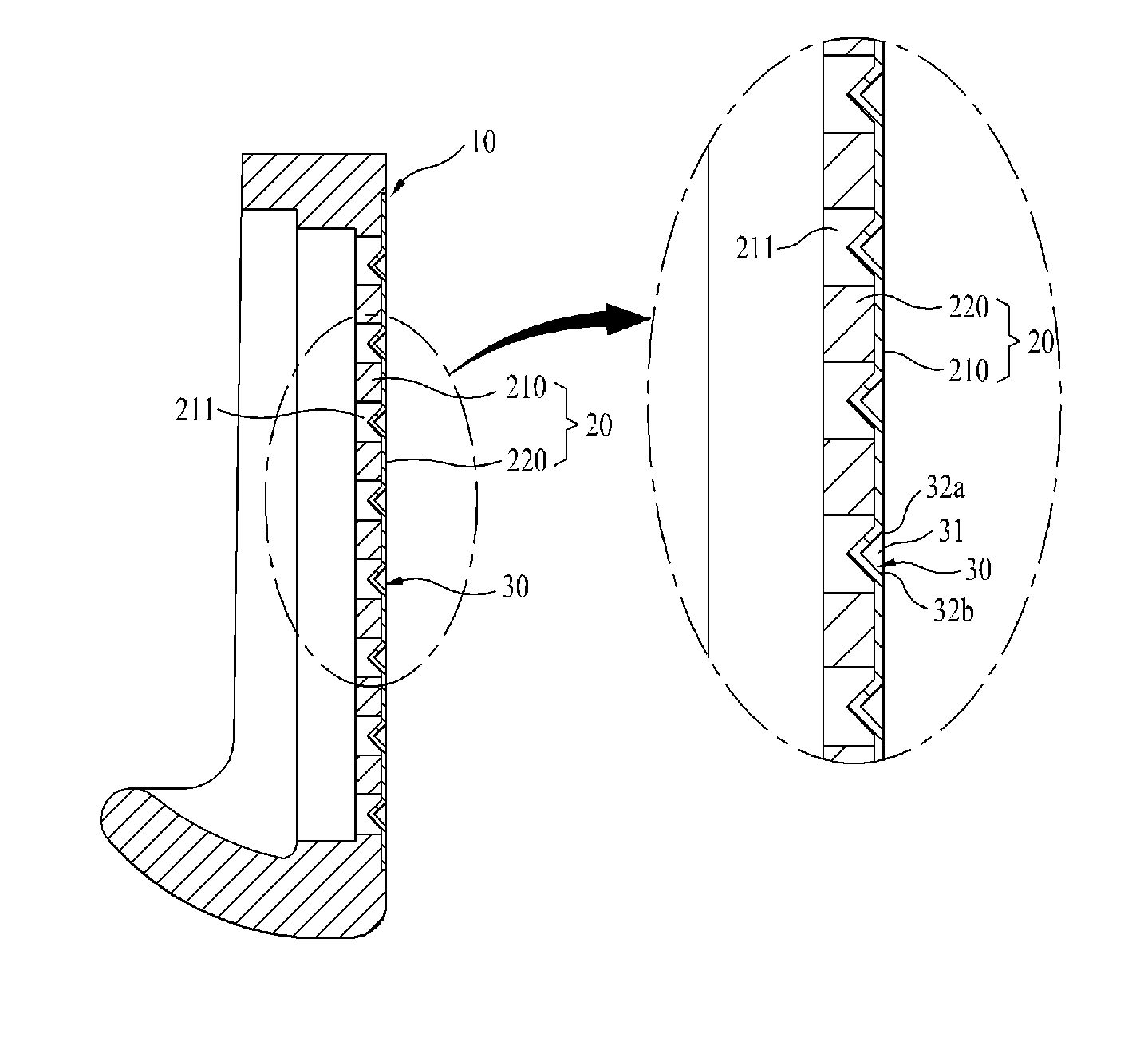
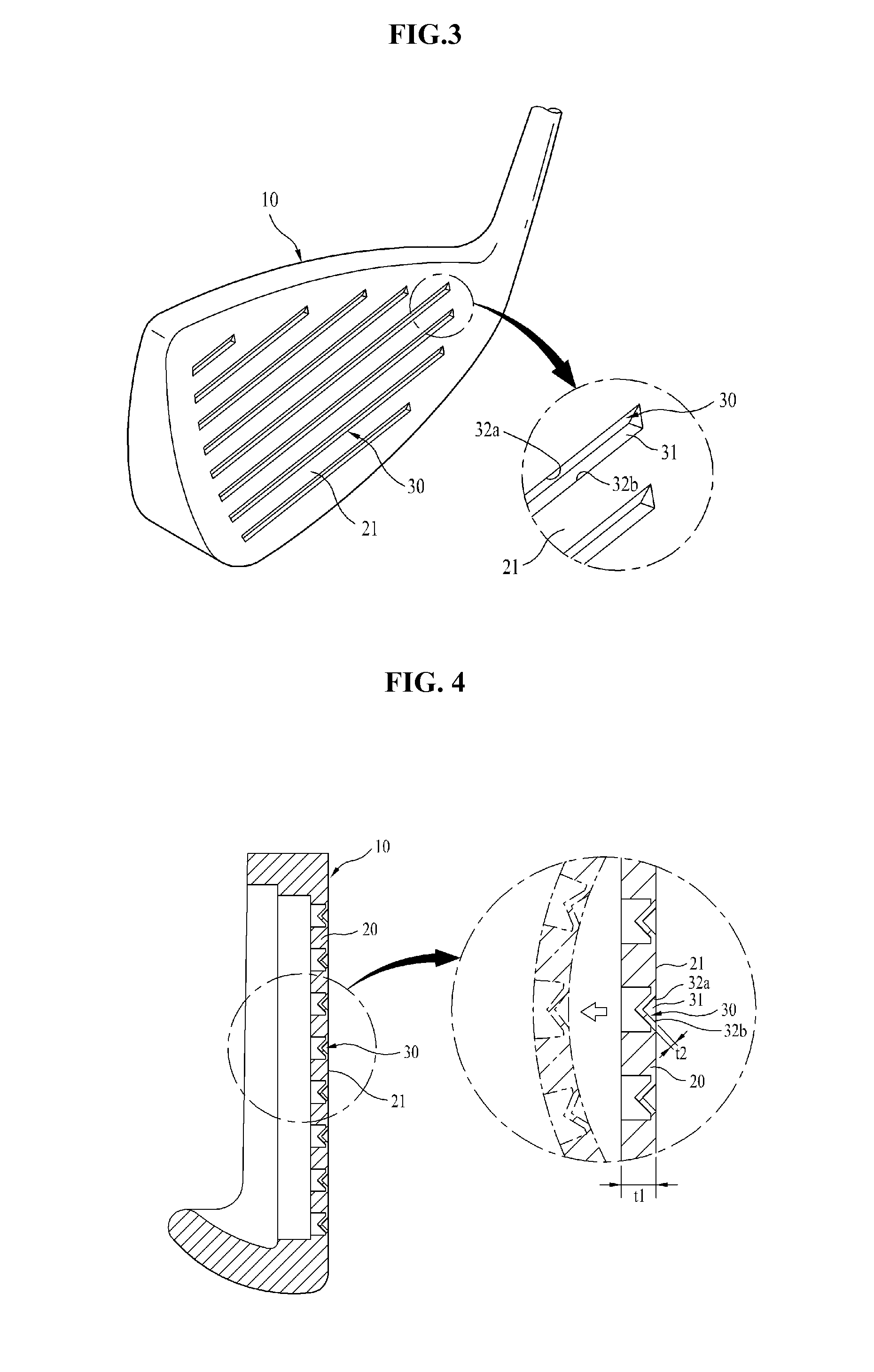
[0029]FIGS. 3 and 4 are a perspective view and a cross-sectional view showing a golf club head in accordance with the present invention. As shown in drawings, a head 10 includes a striking plate 20 having a striking surface 21 configured to contact a golf ball upon striking. A variation part 30 is longitudinally formed at the striking surface 21 of the striking plate 20.

[0030]The variation part 30 is provided in plural at predetermined intervals in a vertical direction of the striking surface 21, and thus, the striking surface 21 includes a plurality of divisional striking surfaces divided by the variation parts 30 in a vertical direction and longitudinally formed in a lateral direction.

[0031]In addition, the variation part 30 has a thickness t2 smaller than a thickness t1 of the striking plate 20 having the striking surface 21, upper and lower sides continuously formed with the striking surface 20, and a center part concavely formed from the striking surface 21 to form a groove 31 ...

second embodiment

[0039]In addition, according to another variation of the present invention, as shown in FIG. 9(a), the gravity center extension 22 projects rearward from the inner plate 210 to increase rotation moment of the gravity center extension 22 so that anti-slide of a golf ball, stability of a ball-flying direction and a spin function of the golf ball can be further improved. In still another embodiment, as shown in FIG. 9(b), an arc-shaped part 210a and an arc-shaped groove 220a are formed at mutual contact parts of the outer plate 220 and the inner plate 210, respectively, so that slide contact between the inner plate 210 and the outer plate 220 can be smoothly performed when the striking plate 20 is elastically deformed.

[0040]FIG. 10 is a perspective view of a golf club head in accordance with a third embodiment of the present invention. In the configuration of the first embodiment, the variation part 40 in the longitudinal direction crossing the variation part 30 in the lateral directio...


PUM


Abstract

Disclosed is a golf club head including a variation part, which is easily flexible, formed at a striking surface of a head, and capable of increasing repulsive power caused by an elastic deformation rate of the striking surface upon striking a ball to improve a flying distance, and strengthening an elastic recovering force of corner parts formed by the variation part to further enhance stability in a ball-flying direction and a ball spin function.

Description

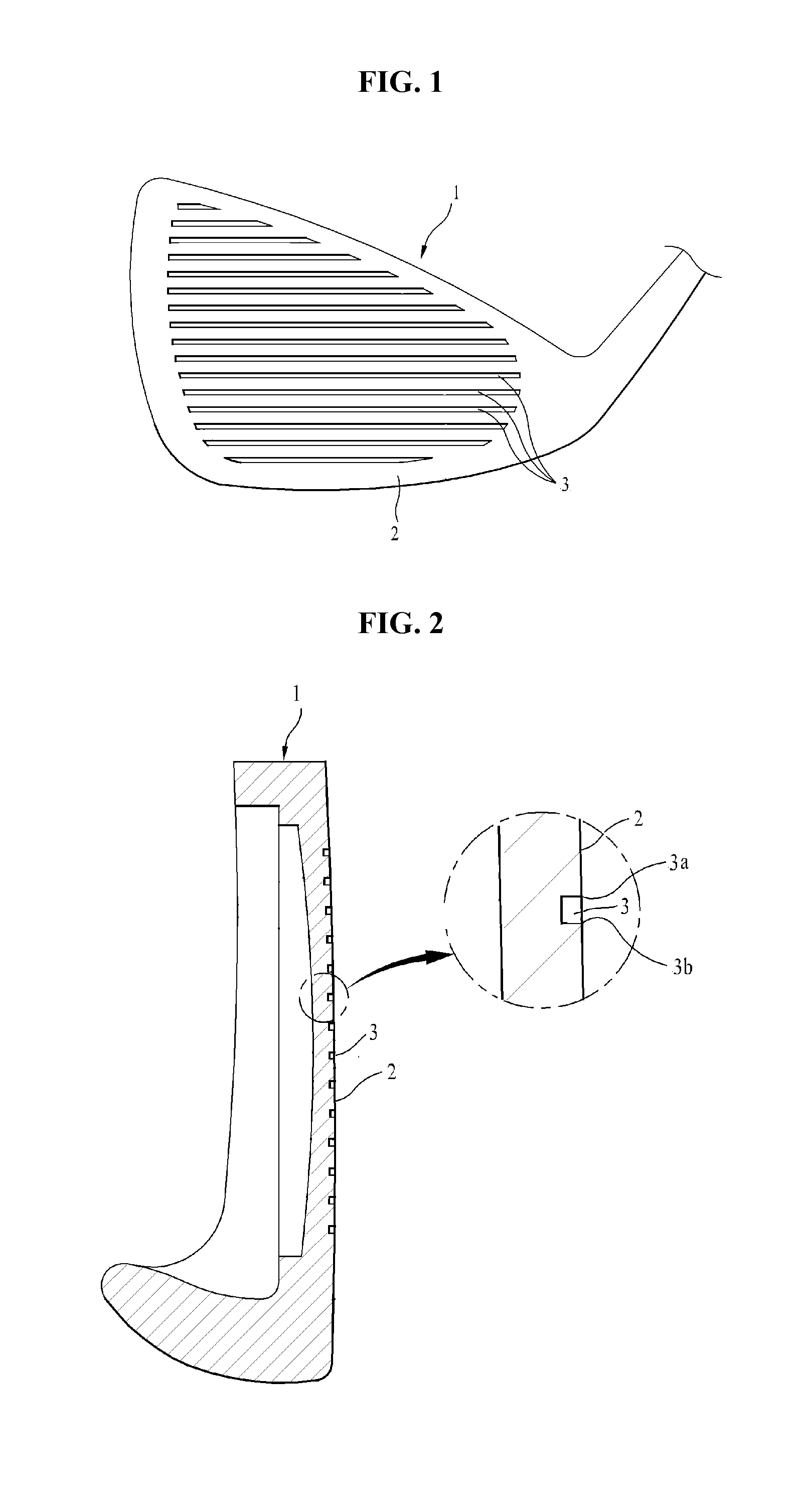
CROSS-REFERENCE TO RELATED APPLICATION[0001]This application claims priority to and the benefit of Korean Patent Application No. 2010-083734, filed on Aug. 28, 2010, the disclosure of which is incorporated herein by reference in its entirety.BACKGROUND[0002]1. Field of the Invention[0003]The present invention relates to a golf club head, and more particularly, to a golf club head capable of improving a repulsive power of a striking surface to increase a driving distance and further improving stability of a ball-flying direction and a spin function of a ball using a corner part of a groove formed on the striking surface.[0004]2. Discussion of Related Art[0005]In general, golf clubs are classified into three kinds, i.e., drivers for causing golf balls to fly a long distance, irons for striking balls onto a green of a fair way, and putters for accurately striking balls on the green to put the balls into holes. A basic configuration of each golf club includes a head having a striking su...

Claims


Application Information

Patent Timeline
Patent Type & Authority Applications(United States)
IPC IPC(8): A63B53/04
CPCA63B53/04A63B53/047A63B2053/0416A63B2053/0445A63B2053/042A63B60/00A63B60/02A63B53/0416A63B53/042A63B53/0445
Inventor LEE, SE-YUP
Owner KOREA NUCLEAR ENG
Learn More