LED tube lamp

Inactive Publication Date: 2012-03-01
HON HAI PRECISION IND CO LTD
View PDF3 Cites 94 Cited by
  • Summary
  • Abstract
  • Description
  • Claims
  • Application Information

AI Technical Summary

Benefits of technology

[0005]Many LED tube lamps include a cylindrical tube, a cover and an LED substrate. However, in order to increase the illumination, a type of LED array including a plurality of LEDs connected in series arranged on the LED substrate is used in LED tube lamps. In another way, the cover is made of transparent or translucent material mixed with light diffusion particles to improve the light scattering effect of the light. However, these improvements are not suitable for local lighting, such as in the case of a wall, showing exhibits in a gallery, which requires sufficient illumination on specific items.
[0005]Many LED tube lamps include a cylindrical tube, a cover and an LED substrate. However, in order to increase the illumination, a type of LED array including a plurality of LEDs connected in series arranged on the LED substrate is used in LED tube lamps. In another way, the cover is made of transparent or translucent material mixed with light diffusion particles to improve the light scattering effect of the light. However, these improvements are not suitable for local lighting, such as in the case of a wall, showing exhibits in a gallery, which requires sufficient illumination on specific items.
[0005]Many LED tube lamps include a cylindrical tube, a cover and an LED substrate. However, in order to increase the illumination, a type of LED array including a plurality of LEDs connected in series arranged on the LED substrate is used in LED tube lamps. In another way, the cover is made of transparent or translucent material mixed with light diffusion particles to improve the light scattering effect of the light. However, these improvements are not suitable for local lighting, such as in the case of a wall, showing exhibits in a gallery, which requires sufficient illumination on specific items.

Problems solved by technology

However, these improvements are not suitable for local lighting, such as in the case of a wall, showing exhibits in a gallery, which requires sufficient illumination on specific items.

Method used


Image

  • LED tube lamp
  • LED tube lamp
  • LED tube lamp

Examples


first embodiment

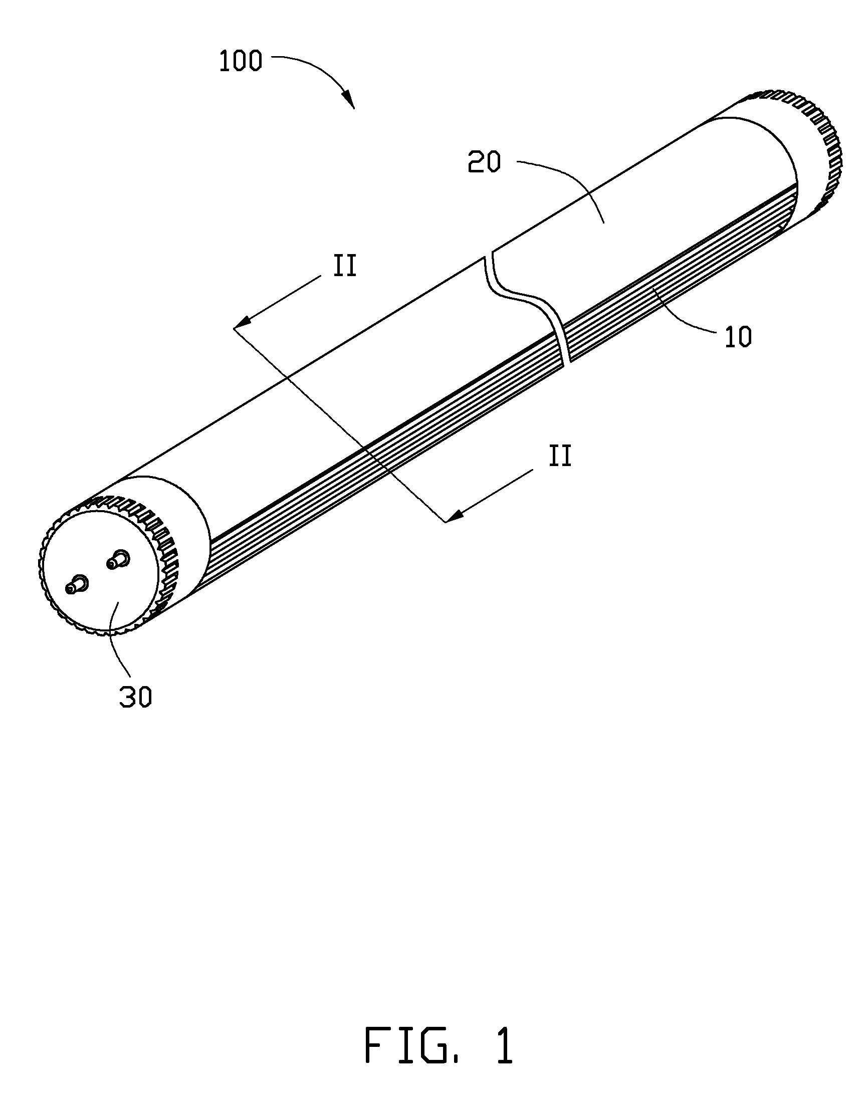
[0018]Referring to FIG. 1, an LED tube lamp 100 is illustrated. The LED tube lamp 100 includes a heat sink 10, a cover 20, and a pair of connectors 30. The cover 20 is fixed to the heat sink 10. The cover has an elongated structure and has an arc-shaped cross section. The connectors 30 are arranged at opposite ends of the LED tube lamp 100 and are used to connect to a connector (not shown), thus electrically connecting the LED tube lamp 100 to a power source.

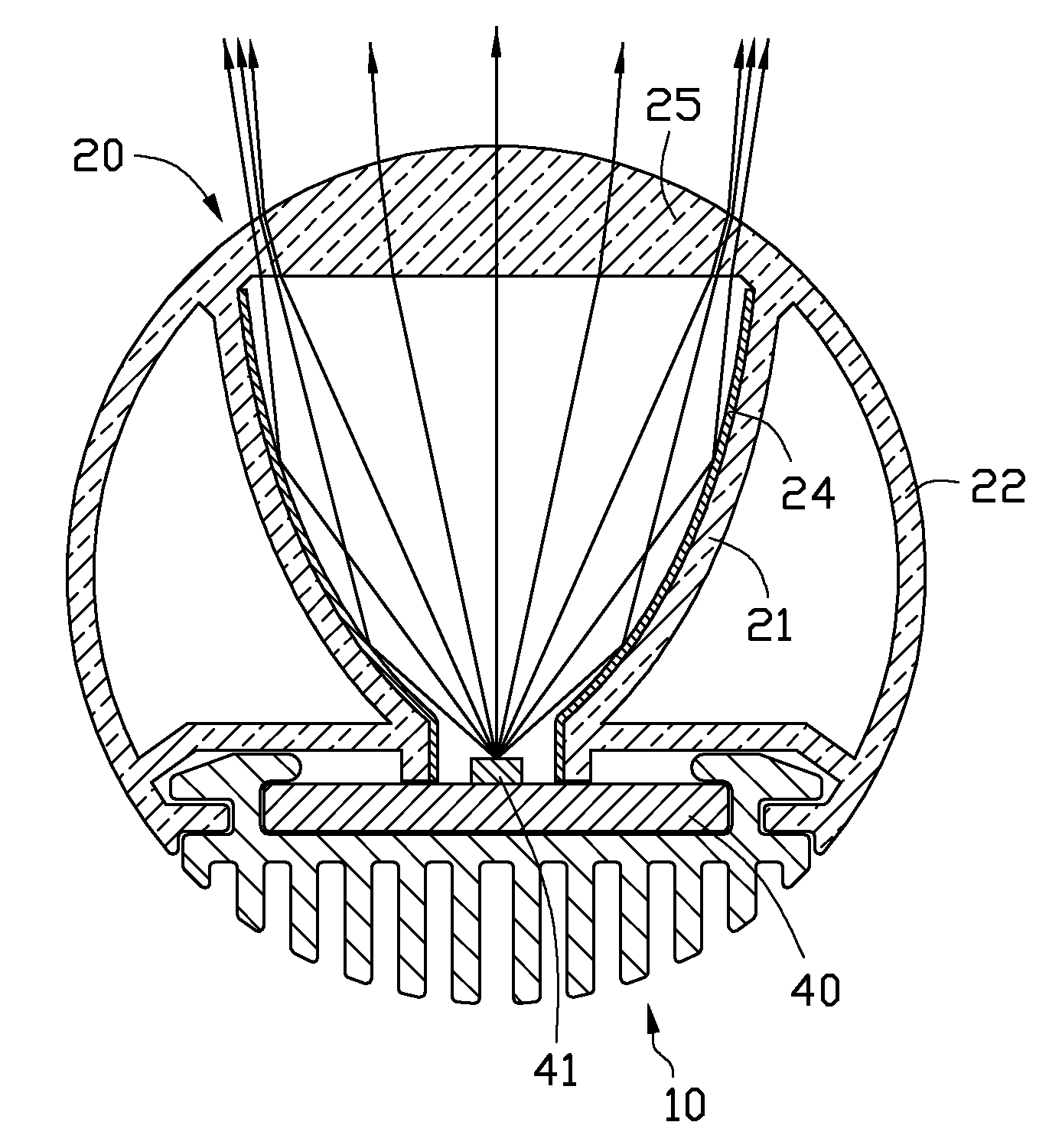
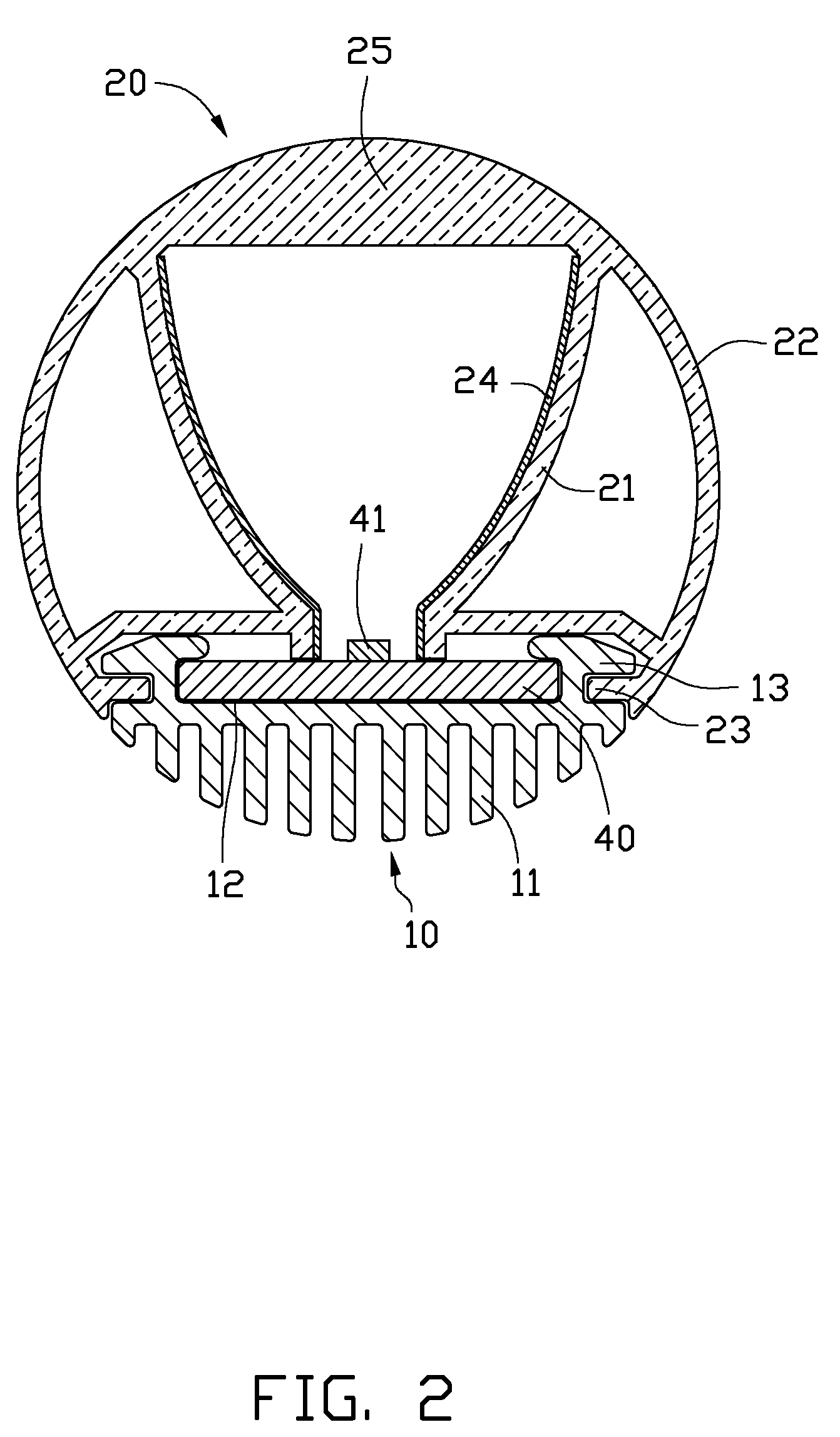
[0019]Referring to FIG. 2, the LED tube lamp 100 further includes an LED substrate 40 mounted on the heat sink 10 and electrically connected to the connector 30. A number of LEDs 41 are arranged on the LED substrate 40. The LEDs 41 can be chosen for having a large light divergence angle, high illumination, and / or can be colored according to actual requirements.

[0020]The heat sink 10 has an elongated structure and is made of metal with good heat conductivity, such as copper or aluminum. In another embodiment, the heat sink 10 can...

second embodiment

[0027]Referring to FIG. 5, an LED tube lamp 102 according a second embodiment is illustrated. The LED tube lamp 102 is similar to the LED tube lamp 100 described above. The LED tube lamp 102 includes a cover (not labeled) and an LED substrate 402 including a number of LEDs 412 arranged thereon. The cover includes a cover body 222 and a light gathering wall 212. The difference between the lamps 102 and 100 is that the cover body 222 and the light gathering wall 212 are the components are independent from each other. The light gathering wall 212 is accommodated in the cover body 222, arranged between the LED substrate 402 and the cover body 222. The light gathering wall 212 is parabolic-shaped in cross section, and the cover body 222 includes a condenser lens 252 facing the light gathering wall 212. The light beams emitting from the LEDs 412 are reflected and are gathered by the light gathering wall 212. The light beams reflected from the light gathering wall 212 are further gathered ...

third embodiment

[0028]Referring to FIG. 6, an LED tube lamp 103 according a third embodiment is illustrated. The LED tube lamp 103 includes a cover (not label) and a LED substrate 403 including a number of LEDs 413 arranged on the LED substrate. The cover includes a cover body 223 and a light gathering wall 213. The difference between the lamps 103 and 100 is that the lamps 103 only employ the light gathering wall 213 to gather light. The light gathering wall 213 and the cover body 223 are integrally formed. The light gathering wall 213 is a parabolic reflector with a parabolic-shaped cross section. In this embodiment, the light gathering wall 213 is a parabolic reflector. The parabolic reflector can be defined to direct appropriate direction. The light beams exiting from the light gathering wall 213 pass through the cover 223 and spread out. The light beams can be oriented on the light gathering wall 213, and be employed to illuminate a certain region requiring sufficient illumination.


PUM

PropertyMeasurementUnit
Transparencyaaaaaaaaaa
Lightaaaaaaaaaa
Reflectionaaaaaaaaaa

Abstract

An LED tube lamp includes a heat sink, an LED substrate, a cover fixed to the heat sink. A light gathering wall arranged between the cover and the LED substrate. The cover further includes a condenser lens, the light gathering wall is configured for reflecting and gathering the light beams emitting from the LEDs, the condenser lens is configured for gathering the light beams reflected from the light gathering wall. The light beams emitting form the LEDs can be controlled substantially in a desired illuminating range after being gathered twice.

Description

BACKGROUND[0001]1. Technical Field[0002]The present disclosure relates to light emitting diode (LED) illuminating devices and, particularly, to an LED tube lamp.[0003]2. Description of Related Art[0004]Compared to traditional light sources, light emitting diodes (LEDs) have many advantages, such as high luminous efficiency, low power consumption, and long service life. LED lamps are widely used in many applications to replace typical fluorescent lamps and neon tube lamps.[0005]Many LED tube lamps include a cylindrical tube, a cover and an LED substrate. However, in order to increase the illumination, a type of LED array including a plurality of LEDs connected in series arranged on the LED substrate is used in LED tube lamps. In another way, the cover is made of transparent or translucent material mixed with light diffusion particles to improve the light scattering effect of the light. However, these improvements are not suitable for local lighting, such as in the case of a wall, sho...

Claims


Application Information

Patent Timeline
IPC IPC(8): F21V29/00
CPCF21K9/17F21Y2103/003F21Y2101/02F21V13/04F21V3/02F21V7/005F21V29/763F21V29/767F21K9/27F21K9/66F21K9/68F21K9/69F21Y2103/10F21Y2115/10F21V3/061F21V3/062
Inventor CHANG, SHAO-HAN
Owner HON HAI PRECISION IND CO LTD
Why Eureka
Try Eureka