Eureka AIR delivers breakthrough ideas for toughest innovation challenges, trusted by R&D personnel around the world.

Inorganic perovskite solar cell based on ordered SnO2 nanorod array and preparation method of inorganic perovskite solar cell

A nanorod array and solar cell technology, applied in the field of solar cells, can solve the problems of difficult control of array density and nanorods, difficult extraction of photogenerated charges, poor interface contact, etc., achieve high charge collection efficiency, improve filling and interface contact performance, the effect of accelerating charge transport

Active Publication Date: 2020-10-02
HUBEI UNIV OF ARTS & SCI
View PDF14 Cites 4 Cited by
  • Summary
  • Abstract
  • Description
  • Claims
  • Application Information

AI Technical Summary

Problems solved by technology

At present, there are already SnO prepared by Huang S.M., Mullerbuschbaum P. and Zhang Wenhua. 2 Nanorod arrays are used in perovskite solar cells (reference documents: Electrochim.Acta, 2018, 283:1134, J.Power Sources, 2018, 402:460, patent CN108493346A), but the following problems generally exist: SnO 2 It is difficult to control the array density and nanorod gap of the nanorod array while pursuing the length of the rod. Too small array density results in fewer interfaces between the nanorods and the perovskite layer in devices with the same area, and the photogenerated electrons from the perovskite layer The extraction effect to the nanorods is poor; on the contrary, the excessive density of the array leads to too small gaps between the nanorods, and the permeability of the subsequent perovskite layer to the nanorod array and the interface contact between the two are poor, resulting in photogenerated charge extraction difficulty

Method used


Image

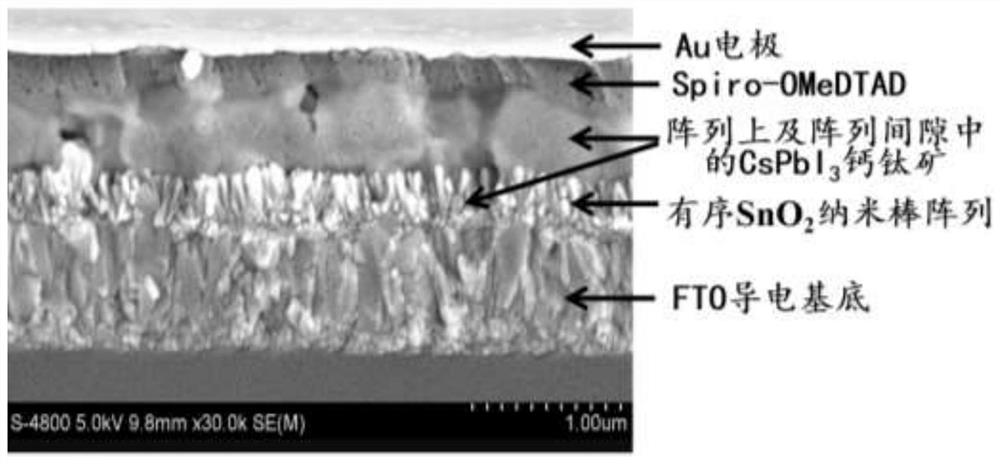
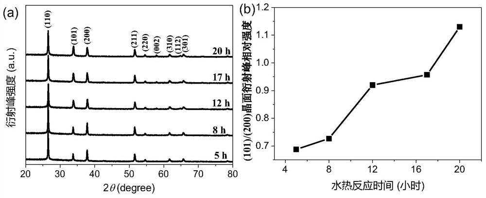
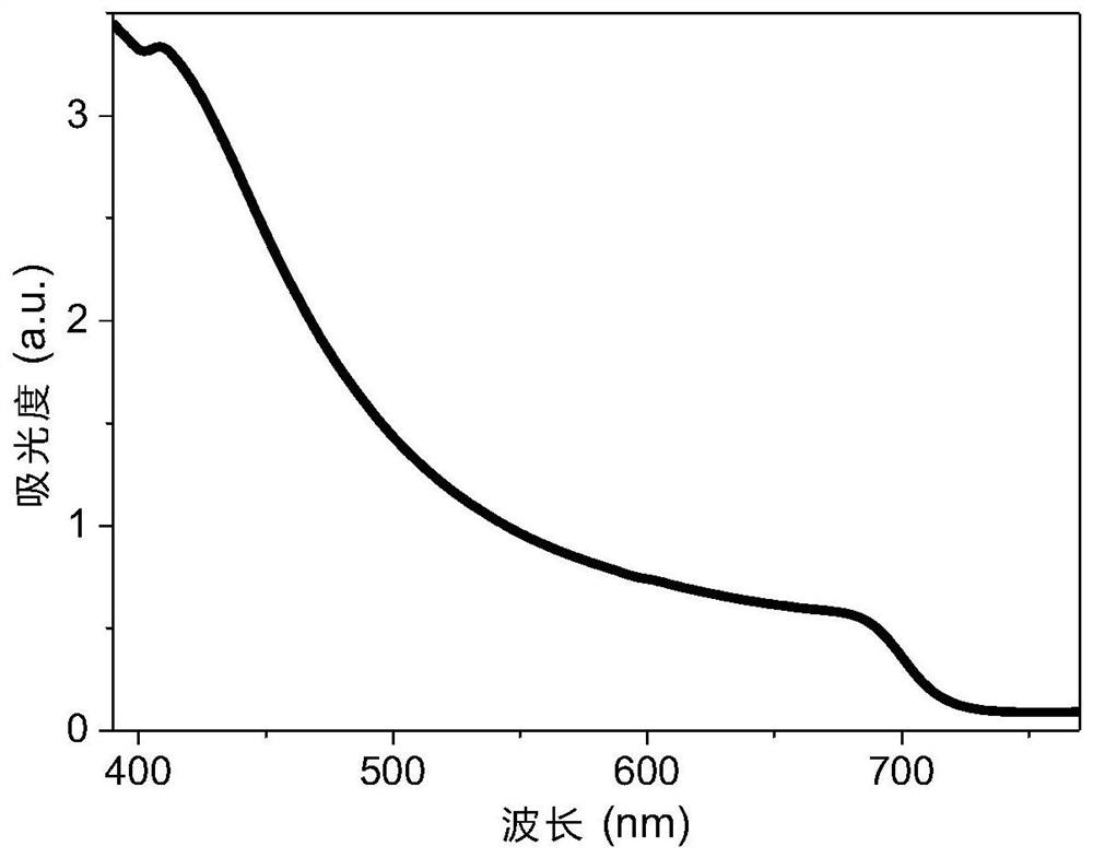
  • Inorganic perovskite solar cell based on ordered SnO2 nanorod array and preparation method of inorganic perovskite solar cell
  • Inorganic perovskite solar cell based on ordered SnO2 nanorod array and preparation method of inorganic perovskite solar cell
  • Inorganic perovskite solar cell based on ordered SnO2 nanorod array and preparation method of inorganic perovskite solar cell

Examples


Embodiment 1

[0032] Step 1. Prepare 0.01mol / L SnCl in a nitrogen glove box 2 2H 2 The isopropanol solution of O was refluxed and condensed at 70°C for 1 hour, and filtered through a syringe filter with a pore size of 0.22 μm to obtain a pale yellow seed solution. The cleaned conductive substrate was bombarded with Plasma plasma for 5 minutes. Next, the conductive substrate was placed on a spin coater, and the above-prepared seed crystal solution was added dropwise on the conductive substrate, firstly spin-coated at a speed of 1000 rpm for 10 seconds, and then spin-coated at a speed of 3000 rpm for 20 seconds. Finally, the spin-coated film is sintered at 150°C for 30 minutes, and grown on a conductive substrate to obtain SnO 2 seed layer.

[0033] Step two:

[0034] (a) Add ultrapure water, ethanol, concentrated hydrochloric acid, SnCl to the reagent bottle in sequence 4 ·5H 2 O and NaCl were mixed while adding and mixed to prepare a solution containing 0.002mol / L SnCl 4 ·5H 2 Hydro...


PUM

PropertyMeasurementUnit
thicknessaaaaaaaaaa
thicknessaaaaaaaaaa
diameteraaaaaaaaaa

Abstract

The invention relates to the field of solar cells, specifically, relates to an inorganic perovskite solar cell based on an ordered SnO2 nanorod array and a preparation method of inorganic perovskite solar cell. The inorganic perovskite solar cell comprises a conductive substrate, a SnO2 seed crystal layer deposited on the surface of the conductive substrate, a SnO2 seed crystal layer, a SnO2 nanorod array growing on the surface of the SnO2 seed crystal layer, an inorganic perovskite layer deposited in gaps of SnO2 nanorods and on the surfaces of the SnO2 nanorods, a hole transport layer deposited on the surface of the inorganic perovskite layer, and an Au electrode layer deposited on the surface of the hole transport layer. The inorganic perovskite solar cell provided by the invention hasthe advantages of fast charge transmission, high charge extraction efficiency, high photoelectric conversion efficiency, good device stability and the like. The preparation method is simple and convenient to operate, is low in cost and wide in application range, and the prepared solar cell is stable and efficient.

Description

technical field [0001] The invention relates to the field of solar cells, in particular, to an ordered SnO-based 2 Inorganic perovskite solar cells with nanorod arrays and methods for their preparation. Background technique [0002] Perovskite solar cells are considered as a new type of solar cells that can replace monocrystalline silicon due to their high photoelectric conversion efficiency and low production cost. At present, the photoelectric conversion efficiency of organic-inorganic hybrid perovskite solar cells has reached more than 24%, but its commercial application is limited due to the moisture and thermal stability of its own materials. Therefore, the development of stable and efficient inorganic perovskite batteries has become a research hotspot. [0003] Electron transport layer (ETL) is an important part of perovskite solar cells. From the perspective of cell structure, the electron transport layer is in close contact with the perovskite light-absorbing layer...

Claims


Application Information

Patent Timeline
Patent Type & Authority Applications(China)
IPC IPC(8): H01L31/032H01L31/06H01L31/18B82Y30/00
CPCH01L31/032H01L31/06H01L31/18B82Y30/00Y02E10/50Y02P70/50
Inventor 梁桂杰陈美华杨高元李望南王松程晓红徐可
Owner HUBEI UNIV OF ARTS & SCI
Why Eureka
Eureka Blog
Learn More