Battery management circuit, battery module and battery management method
- Summary
- Abstract
- Description
- Claims
- Application Information
AI Technical Summary
Benefits of technology
Problems solved by technology
Method used
Image
Examples
first embodiment
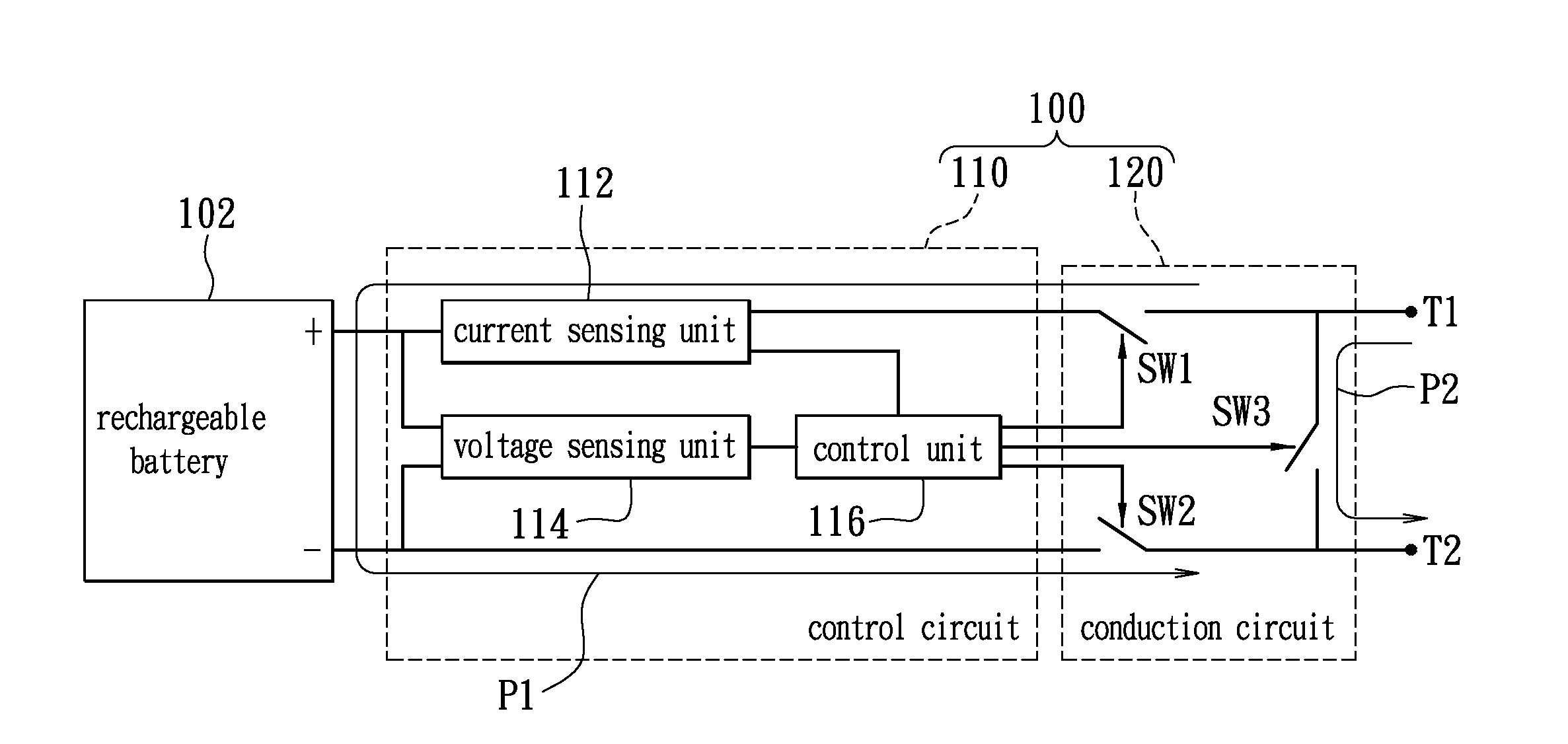
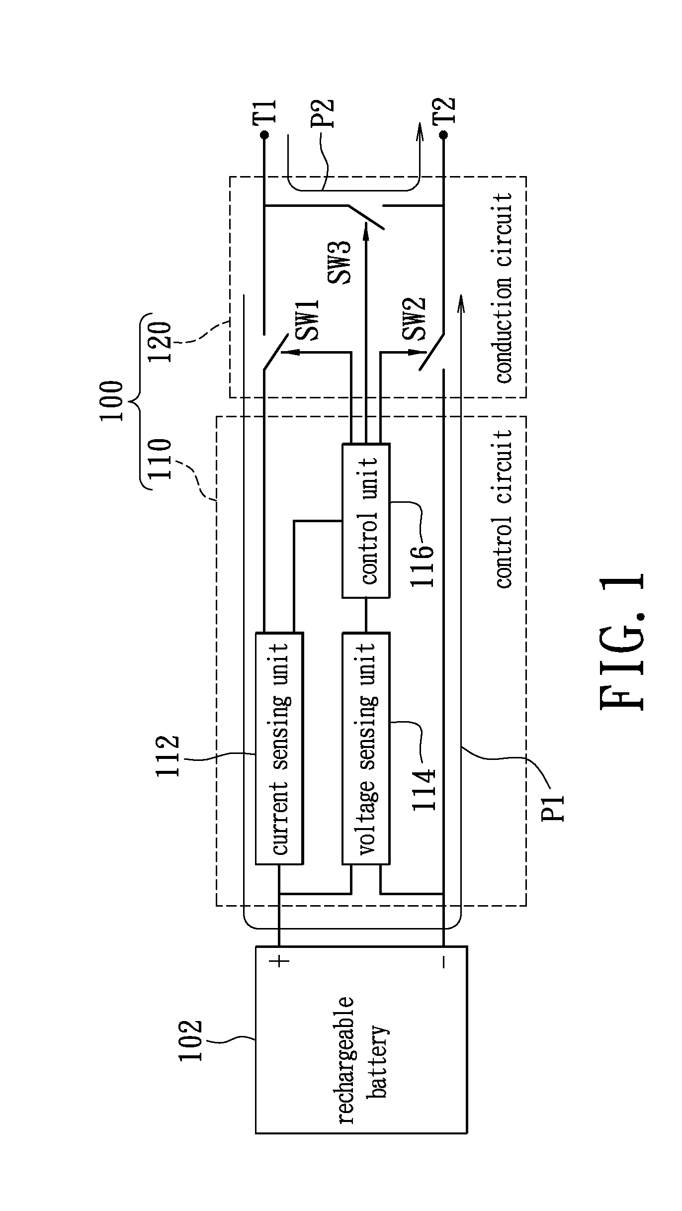
[0025]FIG. 1 shows schematic diagram of a battery management according to the first embodiment of the present disclosure. The battery management circuit 100 is suitable for managing the charge / discharge procedures of a rechargeable battery 102. The battery management circuit 100 includes a control circuit 110 and a conduction circuit 120. The control circuit 110 is coupled to the conduction circuit 120 and a rechargeable battery 102. The conduction circuit 120 is coupled to a positive electrode and a negative electrode of the rechargeable battery 102. The control circuit 110 includes a current sensing unit 112, a voltage sensing unit 114 and a control unit 116, wherein the current sensing unit 112 is coupled to the positive electrode of the rechargeable battery 102 for sensing a current value flowing through the rechargeable battery 102, and the voltage sensing unit 114 is coupled to the positive and negative electrodes of the rechargeable battery 102 for sensing the battery voltage...
second embodiment
[0035]The present disclosure further provides a battery module, as depicted in FIG. 3. FIG. 3 shows a schematic diagram of a battery module according to a second embodiment of the present disclosure. The battery module 300 includes a plurality of battery sets 310, a backup battery set 320, a power path circuit 330, a controller 340 and a voltage sensing unit 350. Each of the battery sets 310 and the backup battery set 320 has a plurality of rechargeable batteries which may be connected in series or in parallel. The power path circuit 330 is coupled to all the battery sets 310 and the backup battery set 320 for switching the conduction paths of the battery sets 310 and the backup battery set 320. The voltage sensing unit 350 is coupled to the power path circuit 330 for sensing whether the voltage of the individual battery set 310 is normal. The controller 340 is coupled to the voltage sensing unit 350 and the power path circuit 330.
[0036]The controller 340 is able to determine whethe...
third embodiment
[0037]A battery management method can be derived based on preceding embodiments. Please refer to FIG. 4, which shows a flow chart of battery management method according to a third embodiment of the present disclosure. First, the method provides a plurality of channels which are coupled to a plurality of power units respectively, where each power unit has a rechargeable battery (step S410), and then the states of charge of the rechargeable batteries are detected through the channels respectively (S420). Next, the charge / discharge paths of the rechargeable batteries are respectively controlled according to the states of charge of the rechargeable batteries (S430).
[0038]In step S430, a first conduction path and a second conduction path are further provided to each rechargeable battery, wherein the first conduction path passes through the corresponding rechargeable battery and the second conduction path does not passes through the corresponding rechargeable battery. The first conduction...
PUM
 Abstract
Description
Claims
Application Information
 - R&D
- Intellectual Property
- Life Sciences
- Materials
- Tech Scout
- Unparalleled Data Quality
- Higher Quality Content
- 60% Fewer Hallucinations
Browse by: Latest US Patents, China's latest patents, Technical Efficacy Thesaurus, Application Domain, Technology Topic, Popular Technical Reports.
© 2025 PatSnap. All rights reserved.Legal|Privacy policy|Modern Slavery Act Transparency Statement|Sitemap|About US| Contact US: help@patsnap.com


