Semiconductor device
a technology of semiconductors and capacitors, applied in the direction of solid-state devices, digital storage, instruments, etc., can solve the problems of short data holding period, difficult to sufficiently reduce power consumption, and loss of electric charge in capacitors, etc., to achieve sufficient power consumption reduction, high speed, and extremely low frequency of refresh operation
- Summary
- Abstract
- Description
- Claims
- Application Information
AI Technical Summary
Benefits of technology
Problems solved by technology
Method used
Image
Examples
embodiment 1
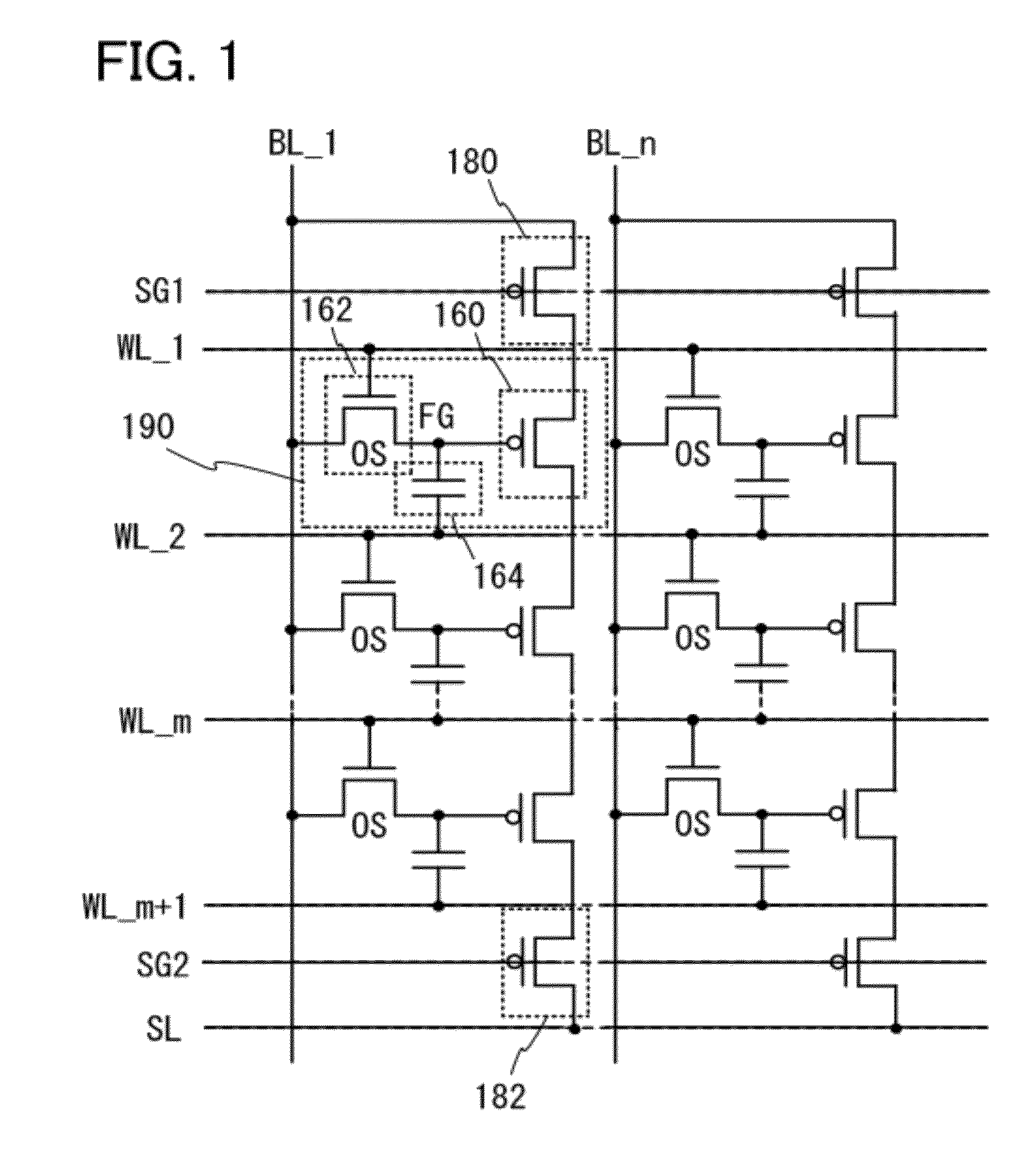
[0057]In this embodiment, a circuit configuration and operation of a semiconductor device according to one embodiment of the invention disclosed herein will be described with reference to the drawings. Note that in the circuit diagrams, “OS” may be written beside a transistor in order to indicate that the transistor includes an oxide semiconductor.
[0058]FIG. 1 illustrates an example of a circuit configuration of a semiconductor device according to one embodiment of the present invention. A structure including a first transistor 160, a second transistor 162, and a capacitor 164 is a memory cell 190. The structure in FIG. 1 includes n columns, and m memory cells 190 are included in each of the columns. Note that m and n are natural numbers.
[0059]Note that there is no particular limitation on the first transistor 160. In terms of increasing the speed of reading data, it is preferable to use, for example, a transistor with high switching rate, such as a transistor including single cryst...
embodiment 2
[0120]In this embodiment, a structure and a manufacturing method of a semiconductor device according to one embodiment of the invention disclosed herein will be described with reference to drawings.
[0121]FIGS. 5A and 5B illustrate an example of the structure of the semiconductor device (the memory cell 190 and the first selection transistor 180) illustrated in the circuit diagram of FIG. 1. FIGS. 5A and 5B are a cross-sectional view and a plan view, respectively, of the semiconductor device. Here, FIG. 5A corresponds to a cross section along line A1-A2 in FIG. 5B. In FIG. 5B, the direction along A1-A2 is the column direction in the circuit diagram of FIG. 1, and the direction perpendicular to A1-A2 is the row direction in the circuit diagram of FIG. 1. Note that in FIG. 5B, wirings (electrodes) or the like are emphasized and insulating layers or the like are omitted for simple explanation.
[0122]In the semiconductor device illustrated in FIGS. 5A and 5B, the first transistor 160 and ...
embodiment 3
[0259]The actually measured field-effect mobility of an insulated gate transistor can be lower than its original mobility because of a variety of reasons; this phenomenon occurs not only in the case of using an oxide semiconductor. One of the reasons that reduce the mobility is a defect inside a semiconductor or a defect at an interface between the semiconductor and an insulating film. When a Levinson model is used, the field-effect mobility on the assumption that no defect exists inside the semiconductor can be calculated theoretically.
[0260]Assuming that the original mobility and the measured field-effect mobility of a semiconductor are μ0 and μ, respectively, and a potential barrier (such as a grain boundary) exists in the semiconductor, the measured field-effect mobility can be expressed as the following formula.
μ=μ0exp(-EkT)[FORMULA2]
[0261]Here, E represents the height of the potential barrier, k represents the Boltzmann constant, and T represents the absolute temperature. When...
PUM
 Abstract
Description
Claims
Application Information
 - R&D
- Intellectual Property
- Life Sciences
- Materials
- Tech Scout
- Unparalleled Data Quality
- Higher Quality Content
- 60% Fewer Hallucinations
Browse by: Latest US Patents, China's latest patents, Technical Efficacy Thesaurus, Application Domain, Technology Topic, Popular Technical Reports.
© 2025 PatSnap. All rights reserved.Legal|Privacy policy|Modern Slavery Act Transparency Statement|Sitemap|About US| Contact US: help@patsnap.com


