Reinforced sandwich structure

a sandwich and reinforcement technology, applied in the field of reinforcement sandwich structure, can solve the problems of non-continuous, laborious and time-consuming, and inability to meet the needs of construction, and achieve the effect of reducing production cost and risk of contamination of futging devi

Inactive Publication Date: 2012-02-02
VDL FIBERTECH IND BV
View PDF17 Cites 3 Cited by
  • Summary
  • Abstract
  • Description
  • Claims
  • Application Information

AI Technical Summary

Benefits of technology

[0014]The presence of such an insert in the core material of the reinforced sandwich structure has been found to improve the bending resistance and stiffness of the structure. Thereby it has been found that the improvement is not limited to the direction in which the inserts extend, but that it extends to a wide variety of other directions. It has further been found that the presence of these inserts contributes to increasing the shear resistance of the core. Shear forces are particularly important with a core made of a foamed plastic and may cause the formation of unwanted smaller or larger cracks in the core material, in particular with a core comprising a foamed material. The presence of the claimed inserts further contributes to improving the resistance of the reinforced sandwich structure against fatigue. Fatigue stresses often entail an unwanted weakening and deflection of a sandwich structure.
[0034]According to a preferred method of this invention the laminate is only impregnated with a resin material using pulltrusion, after the top and bottom layer and core have been interconnected. In that way the risk to contamination of the futging device or of part or all of the tufting needles with resin or damaging the needles, may be minimized.

Problems solved by technology

The sandwich panel disclosed in DE1704872 however presents the disadvantage that the production of the sandwich panel is too time consuming and laborious.
Moreover, since the top and bottom cover sheets are connected to the core by means of an adhesive layer only, the sandwich panel is susceptible to de-lamination.
However, the above disclosed prior art processes are non-continuous, laborious and time consuming.

Method used


Image

  • Reinforced sandwich structure
  • Reinforced sandwich structure
  • Reinforced sandwich structure

Examples


Embodiment Construction

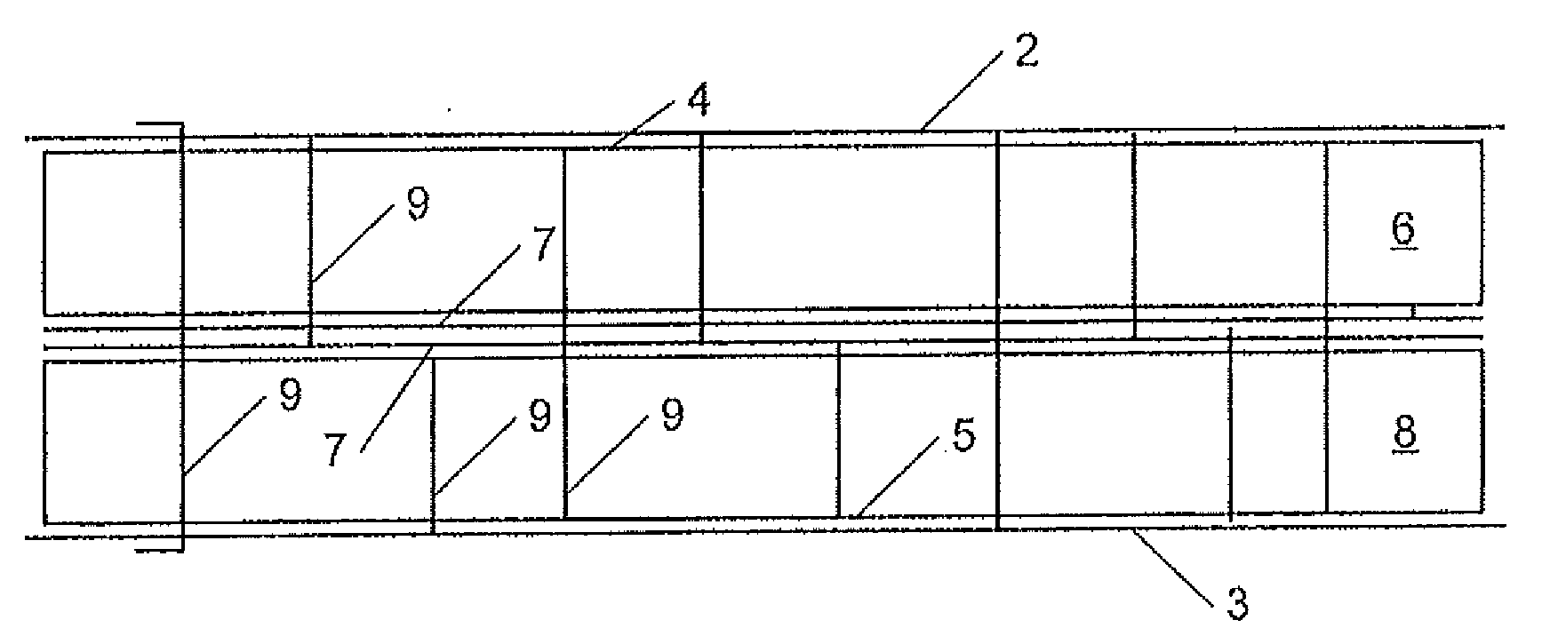
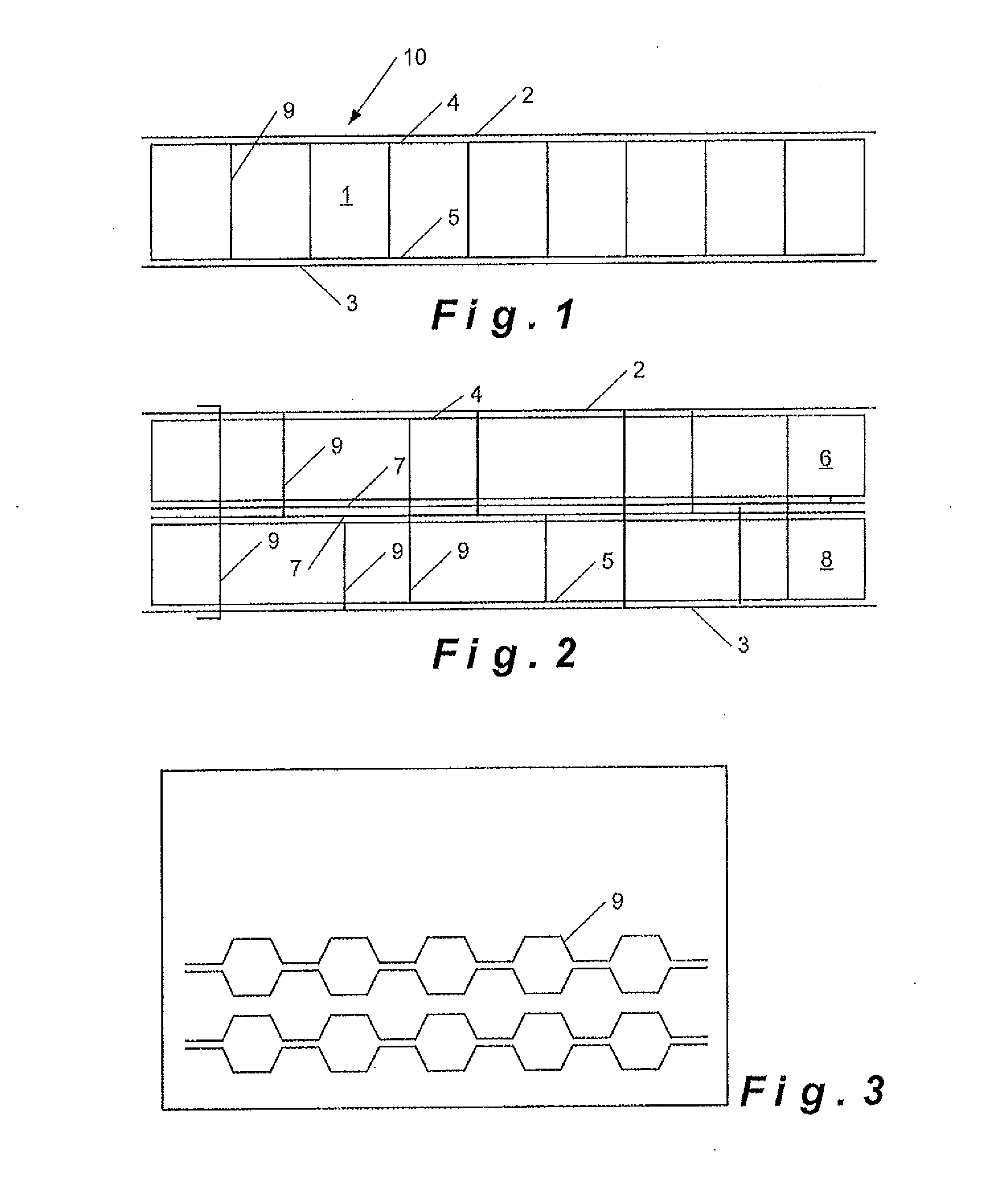
[0040]The reinforced sandwich structure 10 of this invention comprises a core 1 having a top face 4 and a bottom face 5. To the top face 4 a first top layer 2 of the sandwich structure 10 is fastened. To the bottom face 5, a bottom layer 3 of the sandwich structure 10 is fastened.

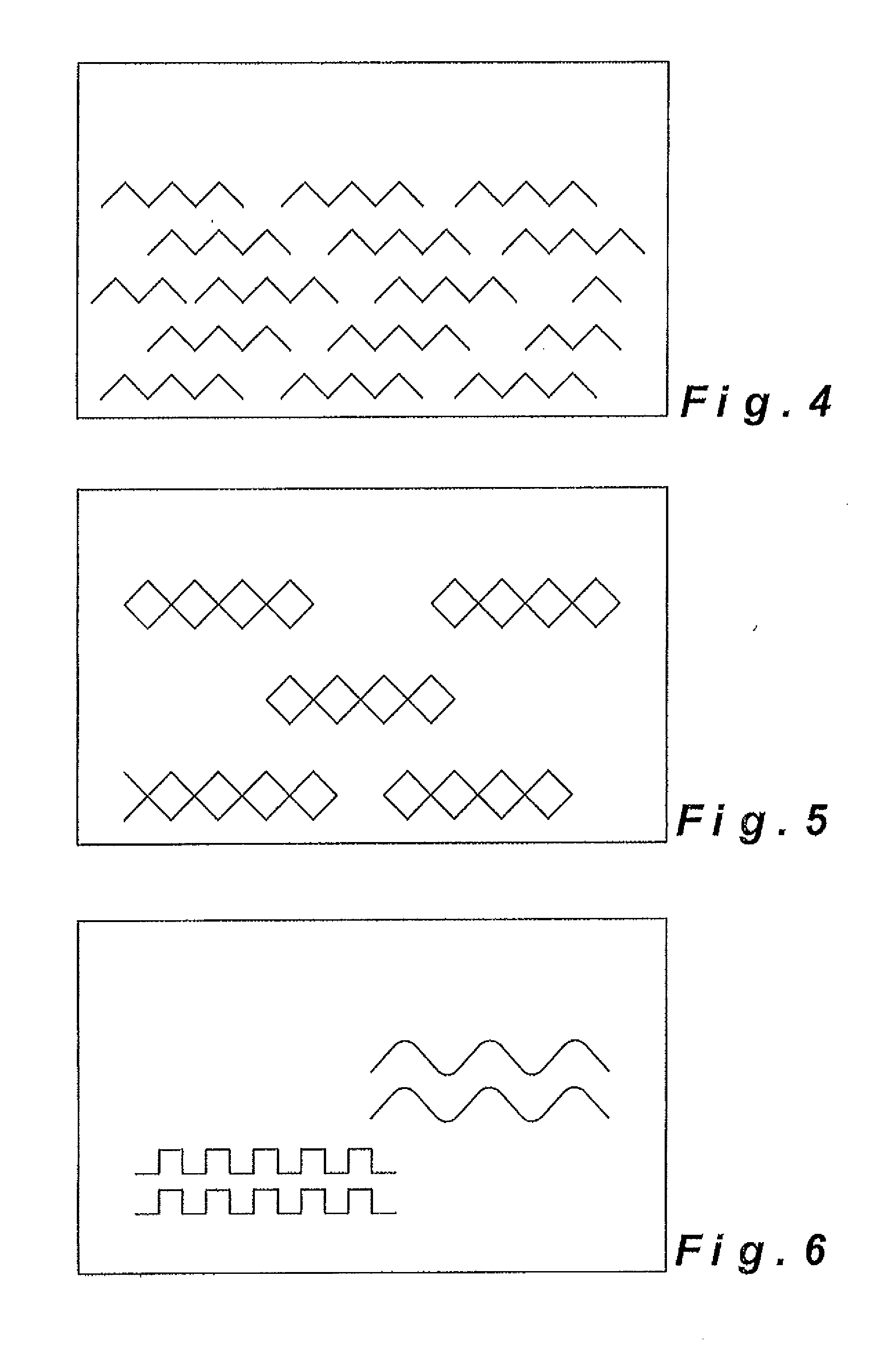
[0041]The core 1, tope layer 2 and bottom layer 3 may be interconnected using conventional fastening techniques known to the person skilled in the art. Examples of known fastening techniques include stitching or needling using a substantially continuous or a non-continuous fibrous reinforcing material. However it is preferred to interconnect top and bottom layer 2, 3 and core 1 by means of tufting using a substantially continuous tow or thread, preferably a substantially continuous fibrous reinforcing material as with this technique the connecting fibrous reinforcing material gets anchored into the top and bottom layer. Thereby, the fibrous reinforcing material may mainly extend in Z-direction, or part of t...


PUM

PropertyMeasurementUnit
lengthsaaaaaaaaaa
lengthsaaaaaaaaaa
heightaaaaaaaaaa

Abstract

A process for forming a reinforced sandwich structure which includes, stacked in height direction thereof, at least one top layer and at least one bottom layer including a fibrous reinforcing material, which top and bottom layer sandwich between them at least one core of a foamed material, the sandwich structure being impregnated with a resin material.The top and bottom layers of fibrous reinforcing material are forwarded along opposite top and bottom faces of the core material to form a multi-layer laminate. A plurality of inserts are inserted in longitudinal and / or transversal direction of the core material interconnecting the top and bottom layer and the core by applying reinforcing fibres at least part of which extend in height direction of the laminate, and the structure is impregnated with a plastic material.

Description

CROSS-REFERENCE TO RELATED APPLICATIONS[0001]This application is a division of U.S. application Ser. No. 11 / 558,536, filed Nov. 20, 2006, which is a continuation-in-part of PCT Application Serial No. PCT / BE2005 / 000075, filed May 11, 2008, each of which are hereby incorporated by reference.BACKGROUND[0002]The present invention relates to a reinforced sandwich structure comprising stacked in height direction thereof at least one top sheet and at least one bottom sheet comprising a fibrous reinforcing material, which top and bottom sheet sandwich between them at least one core of a foamed material, which sandwich structure is impregnated with a resin material to connect the top sheet to a top face of the core and the bottom sheet to a bottom face of the core, as disclosed in the preamble of the first claim.[0003]DE1704872 discloses a method for producing a sandwich panel comprising a core of a foamed plastic material sandwiched between a top and a bottom sheet of a fibrous reinforced p...

Claims


Application Information

Patent Timeline
Patent Type & Authority Applications(United States)
IPC IPC(8): B32B7/08B27N3/04B29C70/24E04C2/36
CPCE04C2/36Y10T428/24033Y10T428/23Y10T428/23914Y10T428/249923Y10T428/249958B29C70/021B29C70/24B29C70/52
Inventor VERHAEGHE, JAN
Owner VDL FIBERTECH IND BV
Why Eureka
Try Eureka