
Induction motor control device and induction motor group control system

a control device and induction motor technology, applied in the direction of digital storage, dynamo-electric motor/converter starter, ac network voltage adjustment, etc., can solve the problems of excessive starting current, increased capacity and loss of “a transmission distribution installation such as a transformer” existing in a distribution line or a distribution system, etc., to reduce the variation of voltag

Active Publication Date: 2012-01-26
SHIMADA RYUICHI
View PDF2 Cites 13 Cited by
  • Summary
  • Abstract
  • Description
  • Claims
  • Application Information

AI Technical Summary

Benefits of technology

[0021]Further, in order to solve the above-described problems, according to another aspect of the present invention, there is provided an induction motor group control system being an induction motor group control system that uses a plurality of the induction motor control devices to control a plurality of induction motors to operate based on power supplied from a three-phase AC power supply, the induction motor group control system including: the plurality of induction motor control devices controlling the plurality of induction motors respectively; a measuring device measuring reactive power based on a combined current of currents flowing into the plurality of induction motor control devices and other loads that are connected to the AC power supply; and a group control device, based on the reactive power measured in the measuring device, generating a command value of reactive power to each of the plurality of induction motor control devices such that the reactive power becomes a predetermined value, and outputting the command value of the reactive power to each of the plurality of induction motor control devices to thereby control the amount of reactive powers generated by the plurality of induction motors, in which a power factor of the entire system composed of the plurality of loads including the plurality of induction motors driven by the AC power supply is controlled.
[0022]Further, in order to solve the above-described problems, according to another aspect of the present invention, there is provided an induction motor group control system being an induction motor group control system that uses a plurality of the induction motor control devices to control a plurality of induction motors to operate based on power supplied from a three-phase AC power supply, the induction motor group control system including: the plurality of induction motor control devices controlling the plurality of induction motors respectively; a measuring device measuring reactive power based on a combined current of currents flowing into the plurality of induction motor control devices and other loads that are connected to the AC power supply; a voltage measuring device measuring voltages of the AC power supply; and a group control device, based on the reactive power measured in the measuring device and the voltages measured in the voltage measuring device, generating a command value of reactive power to each of the plurality of induction motor control devices such that the reactive power becomes reactive power based on the voltages, and outputting the command value of the reactive power to each of the plurality of induction motor control devices to thereby control the amount of reactive powers generated by the plurality of induction motors and reduce variations in the voltages of the AC power supply.

Problems solved by technology

In a factory or the like in particular, the proportion of a motor directly driven by a power supply frequency of 50 Hz, 60 Hz, or the like is large by reason of the increased number of installed motors•the size of capacity, and the like and due to problems of cost•installation space of the inverter, and the like.
Thus, capacity and loss of “a transmission distribution installation such as a transformer” existing in a distribution line or a distribution system are increased.
Further, in a transmission distribution system in general, system reactance at a customer side is inductive due to reactance existing in a wiring, leakage reactance of a transformer, or the like.
The induction motor directly driven by a commercial power supply is simple but has problems on its efficiency at the time of operation, excessive starting current, and the like because it is not electrically controlled.
However, in a large-scale customer, a path from a receiving point to an actual load is long in many cases.
Thus, flowing of current with a low power factor is disadvantageous in terms of loss of a distribution line or capacity of an installation.
Thus, it is not possible for the TSC to continuously control reactive power at a high speed.
Thus, the TCR has a problem that not only the capacitor but also the reactor is needed.
Thus, the SVG has a problem that switching loss increases.
Accordingly, it is not common to employ these conventional reactive power compensation devices for compensation of reactive power in the vicinity of the end of a distribution system.

Method used


Image

  • Induction motor control device and induction motor group control system
  • Induction motor control device and induction motor group control system
  • Induction motor control device and induction motor group control system

Examples


first embodiment

1. Configuration Example and the Like of an Induction Motor Control Device

1-1. The Whole Configuration

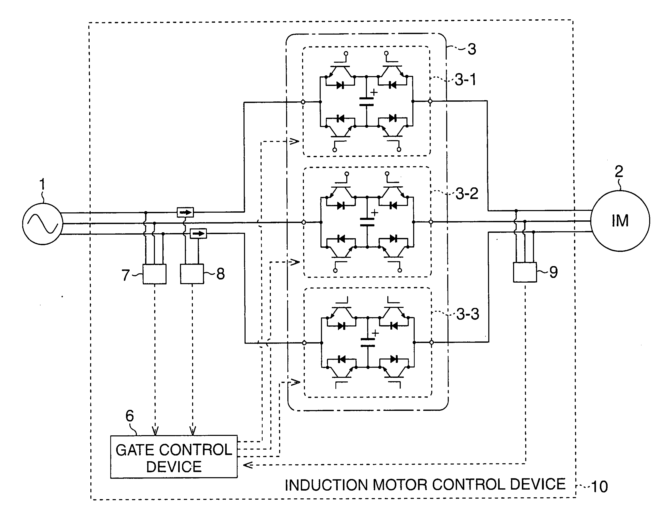
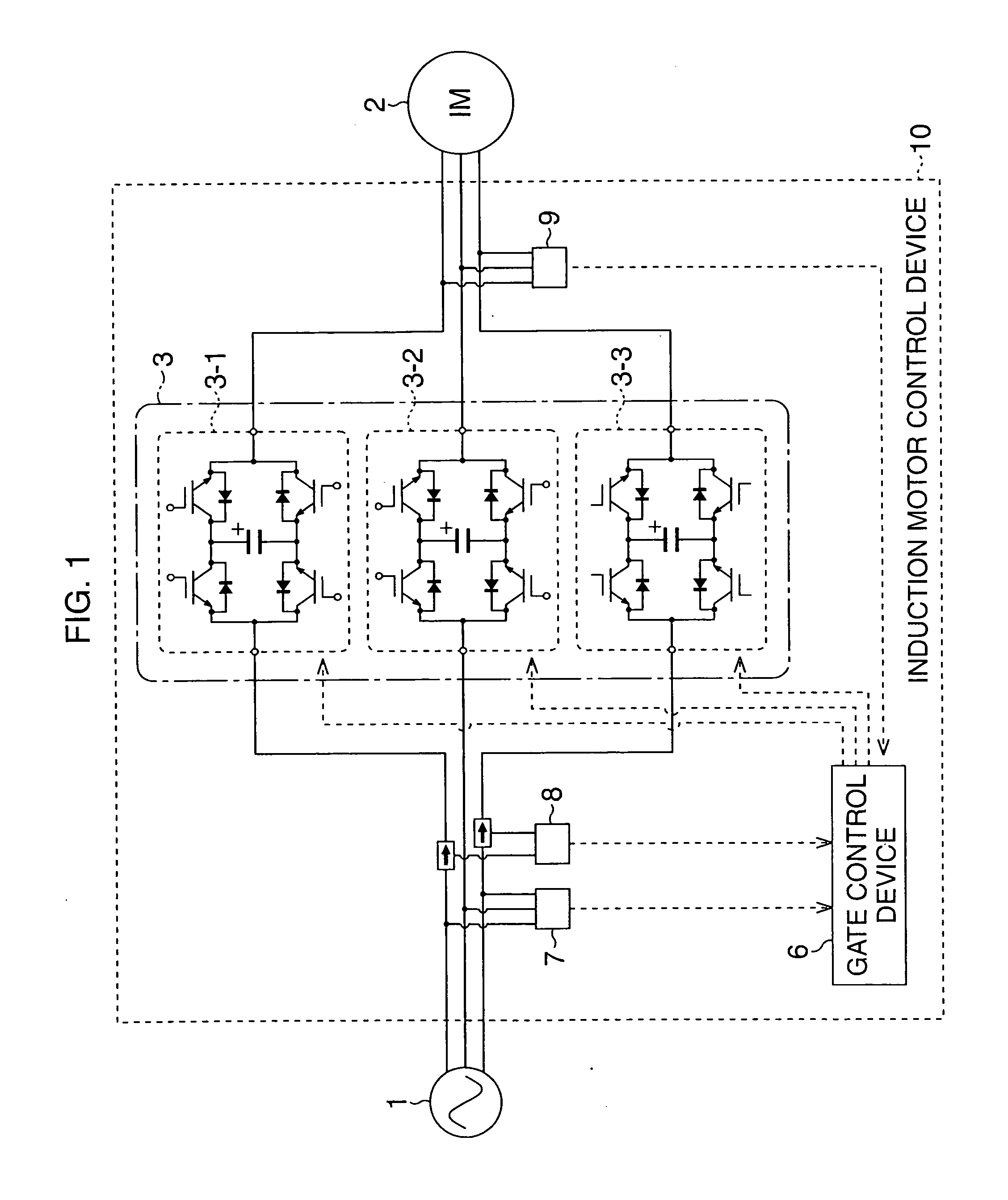
[0034]FIG. 1 shows an outline of one example of a configuration of an induction motor control device according to a first embodiment of the present invention.

[0035]An induction motor control device 10 is configured to include: three magnetic energy recovery switches 3 (magnetic energy recovery switches 3-1 to 3-3); a gate control device 6; a voltage detection device 7; a current detection device 8; and a voltage detection device 9.

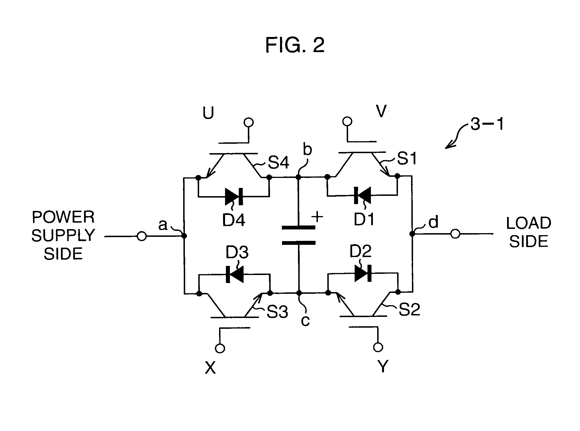
[0036]The magnetic energy recovery switches 3 are each referred to as a MERS (Magnetic Energy Recovery Switch). In this embodiment, a three-phase induction motor 2 is used as a load and a three-phase AC power supply 1 is used, so that the magnetic energy recovery switches 3 (magnetic energy recovery switches 3-1 to 3-3) are provided one by one for respective phases.

[0037]The configuration and operation of the magnetic energy recovery switches 3 are describ...

second embodiment

3. Induction Motor Group Control System

[0077]FIG. 8 is a view showing a configuration example of an induction motor group control system according to a second embodiment of the present invention. The induction motor group control system employs the induction motor control device 10 according to the first embodiment. An induction motor group control system 100 is configured to include: the plurality of induction motor control devices 10 (10-1, 10-2, . . . ); a group control device 11; and a power factor•voltage measuring device 12.

[0078]The plurality of induction motor control devices 10 (10-1, 10-2, . . . ) are connected to an AC power supply 1, and are disposed one by one to correspond to a plurality of induction motors 2 (2-1, 2-2, . . . ), and individually control the plurality of induction motors 2 (2-1, 2-2, . . . ) respectively.

[0079]The group control device 11 gives a command of a generation amount of reactive power to the respective induction motor control devices 10 (10-1, ...


PUM


Abstract

In an induction motor group control system, magnetic energy recovery switches (3) are connected in series to an induction motor (2) directly driven by a commercial power supply, and a plurality of induction motor control devices (10) enabling voltage control and reactive power control of the induction motor 2 are employed to control generation of reactive power so as to maximize a power factor of the entire plurality of AC loads including the induction motor or compensate variations in voltage of an AC power supply (1).

Description

TECHNICAL FIELD[0001]The present invention relates to an induction motor control device and an induction motor group control system, and particularly to a technique suitable for achieving a reduction in reactive power and voltage stabilization in an electric power system having a load including an induction motor therein.BACKGROUND ART[0002]An induction motor among motors is driven relatively easily during operation from its start-up, and further can be used by just being directly connected to a commercial power supply, so that it has been widely employed for various uses.[0003]With recent development of power electronics, it is possible to drive the induction motor at variable speed. That is, alternating-current power is once converted into direct-current power, and by an inverter that inversely converts the direct-current power into alternating-current power different in frequency by switching a semiconductor switch with high frequency, the induction motor is driven. However, a fa...

Claims


Application Information

Patent Timeline
Patent Type & Authority Applications(United States)
IPC IPC(8): H02P25/00H02P5/00
CPCH02J3/1892H02M1/4216H02M5/293H02M2001/008Y02B70/126H02P23/0081H02P23/065H02P27/16H02P5/74H02P23/07H02P23/26Y02B70/10H02M1/008
Inventor FUKUTANI, KAZUHIKONARISAWA, HIDEOSHIMADA, RYUICHIISOBE, TAKANORIKITAHARA, TADAYUKI
Owner SHIMADA RYUICHI
Learn More