
High quality hole cutting using variable shield gas compositions

a technology of shield gas composition and high-quality hole cutting, which is applied in plasma welding apparatus, plasma technique, manufacturing tools, etc., can solve the problems of inability to create high-quality holes using gas combinations, and achieve the effects of maintaining productivity and dross levels, reducing overall part cost, and high quality

Active Publication Date: 2012-01-26
HYPERTHERM INC
View PDF2 Cites 5 Cited by
  • Summary
  • Abstract
  • Description
  • Claims
  • Application Information

AI Technical Summary

Benefits of technology

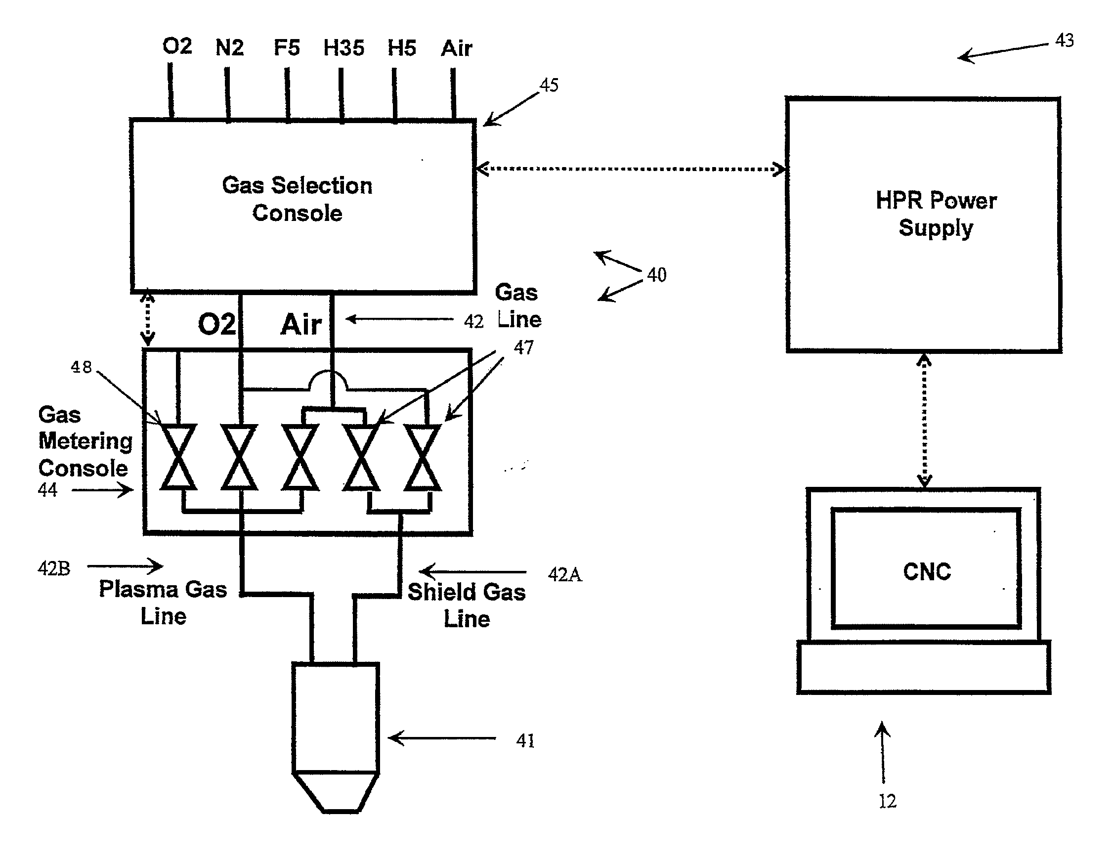
The present invention improves the cutting quality for small internal features in a plasma torch cutting operation by eliminating the need for secondary processes. By changing the shield gas composition when cutting a hole and a contour in a workpiece, the invention eliminates the bevel of the edge of the hole and improves the cutting quality for both features. The invention also includes a plasma torch system with a computer control unit that selects the appropriate shield gas composition for the cutting operation. Overall, the invention improves the efficiency and productivity of plasma torch cutting operations.

Problems solved by technology

For example, though the oxygen plasma gas / air shield gas configuration can cleanly cut large sections with straight edges, such a gas combination is unable to create high quality holes.
This prior method of ensuring hole cut quality was time consuming suggesting that a more efficient method of cutting holes and contours in a single workpiece is necessary.

Method used


Image

  • High quality hole cutting using variable shield gas compositions
  • High quality hole cutting using variable shield gas compositions
  • High quality hole cutting using variable shield gas compositions

Examples


Embodiment Construction

[0034]In the present invention, a first shield gas composition is used when cutting the contour, and a second shield gas composition is used when cutting one or more holes or small internal feature in a single workpiece while using a single plasma torch consumable configuration.

[0035]As used herein, a hole is a shape having a diameter (or dimension) to workpiece (plate) thickness ratio of approximately 2.5 or smaller. Referring to FIG. 3, by way of example, shows a 6×6 inch square piece of 0.5 inch thick plate steel 100 that in one embodiment, could be cut from a larger workpiece (not shown). A 1 inch diameter hole 105 in the 0.5 inch thick plate of steel 100 would have a ratio of 2. A hole, as used herein, can be categorized as a small internal part features that are not necessarily round, but where a majority of the features have dimension that are about 2.5 times or less than the thickness of the materials, for example a 1 inch square 110 in the V2 inch plate steel 100. All other...


PUM

PropertyMeasurementUnit
thickaaaaaaaaaa
diameteraaaaaaaaaa
diameteraaaaaaaaaa

Abstract

A method and apparatus for a plasma torch system having a plasma torch tip configuration that includes a nozzle, an electrode, and a control unit for controlling a composition of the shield gas flow, such that while cutting the contour the shield gas flow comprises a first shield gas composition and while cutting the hole the shield gas flow comprises a second shield gas composition.

Description

CROSS-REFERENCE TO RELATED APPLICATIONS[0001]This application is a continuation application of and claims the benefit of U.S. patent application Ser. No. 12 / 341,731, file on Dec. 22, 2008, the content of which is incorporated herein by reference in its entirety.TECHNICAL FIELD[0002]The invention relates generally to plasma arc cutting torches. More specifically, the invention relates to a method and apparatus for cutting holes and contours in a workpiece using a plasma torch tip configuration.BACKGROUND[0003]Plasma cutting is commonly carried out by using a constricted electric arc to heat a gas flow to the plasma state. The energy from the high temperature plasma flow locally melts the workpiece. For many cutting processes, a secondary gas flow (also known as a shield gas flow, or shield flow) is used to protect the torch and assist the cutting process. The momentum of the high temperature plasma flow and the shield flow help remove the molten material, leaving a channel in the wor...

Claims


Application Information

Patent Timeline
Patent Type & Authority Applications(United States)
IPC IPC(8): B23K10/00
CPCB23K10/00H05H2001/3457H05H1/341H05H1/3457
Inventor LINDSAY, JON W.BEST, GUY T.
Owner HYPERTHERM INC
Learn More