
Laser irradiation device and laser processing method

a laser processing and laser technology, applied in the field of laser irradiation devices and laser processing methods, can solve the problems of deteriorating positional accuracy, impairment of processing efficiency, and difficulty in allowing optical axes of synthesized materials to be sped up, and achieve the effect of less taper

Active Publication Date: 2012-01-19
SEISHIN TRADING
View PDF12 Cites 12 Cited by
  • Summary
  • Abstract
  • Description
  • Claims
  • Application Information

AI Technical Summary

Benefits of technology

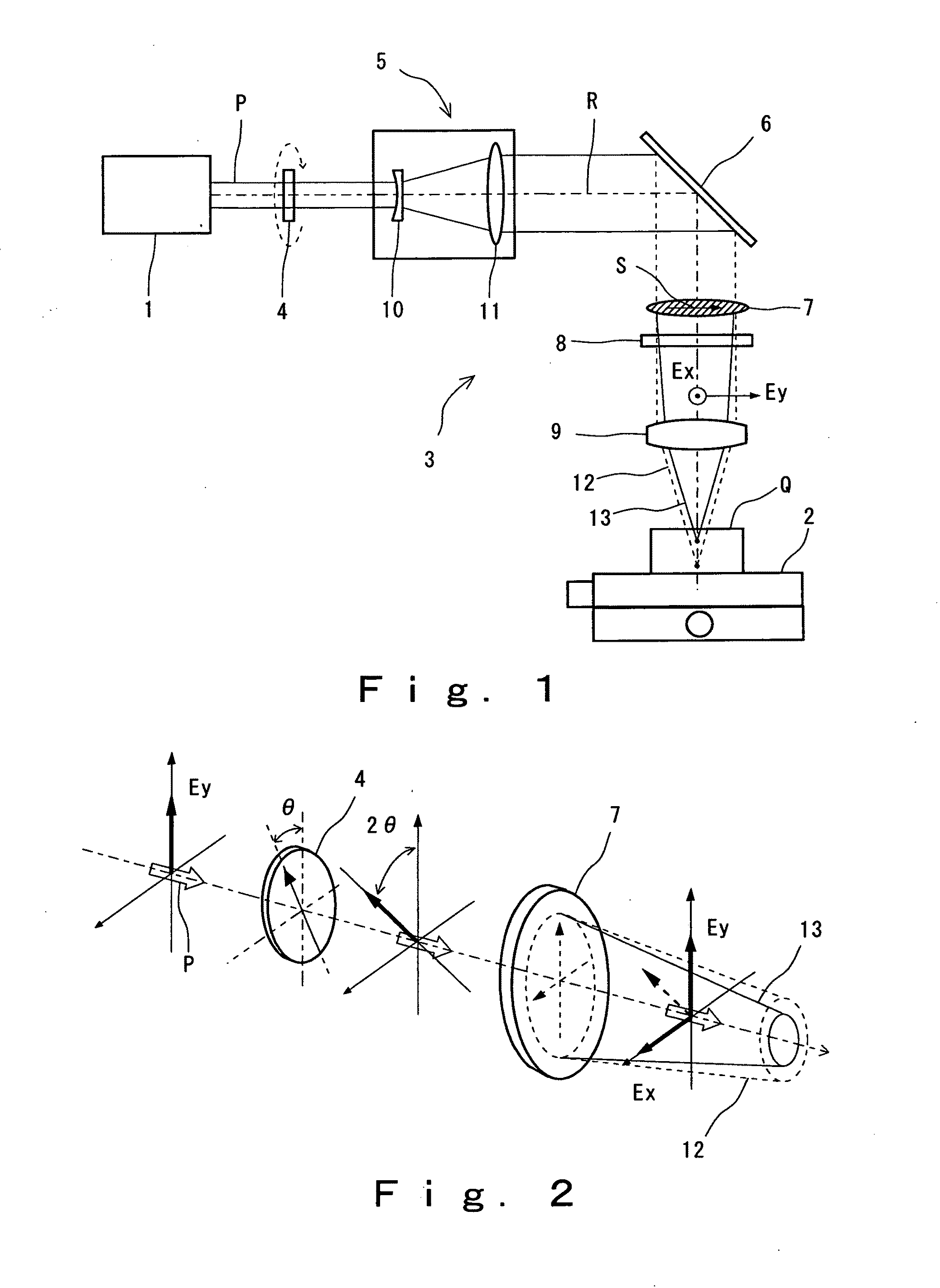
[0027]As explained in the foregoing, the laser irradiation device and the laser processing method of the present invention can surely and easily form a plurality of beam waists, and as a result, fine processing with a great focal depth can be rapidly realized on the target substance. Moreover, by regulating the positions of the plurality of beam waists, the most appropriate processing to meet the type of the processed object (for example, ceramics, glass, sapphire, etc.) can be achieved. It is to be noted that also in hole-opening processing of boards such as green sheets, fine processing accompanied by less taper can be realized.

Problems solved by technology

Further, the above method (B) involves problems in production and preparation as it is difficult to allow optical axes of synthesized two laser beams to agree with one another, and a reflecting surface having a large curvature radius must be provided.
Furthermore, according to the above method (C), there arise problems of impairment of processing efficiency, and deterioration positional accuracy among each of processings, and the like.

Method used


Image

  • Laser irradiation device and laser processing method
  • Laser irradiation device and laser processing method
  • Laser irradiation device and laser processing method

Examples


examples

[0072]Hereinafter, the present invention is explained in detail by way of Examples, but the present invention should not be construed as being limited to these Examples.

experiment 1

Example 1 and Example 2

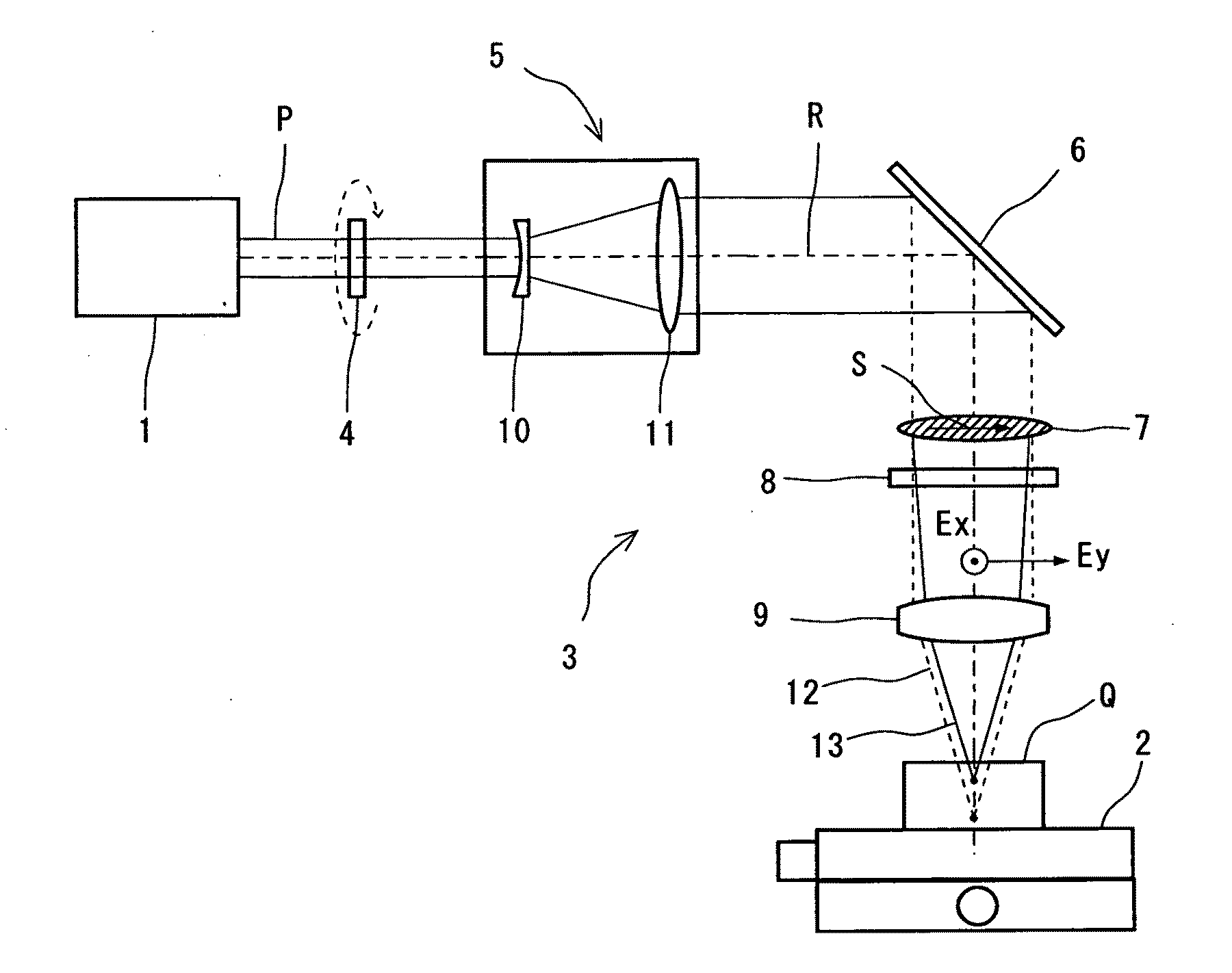
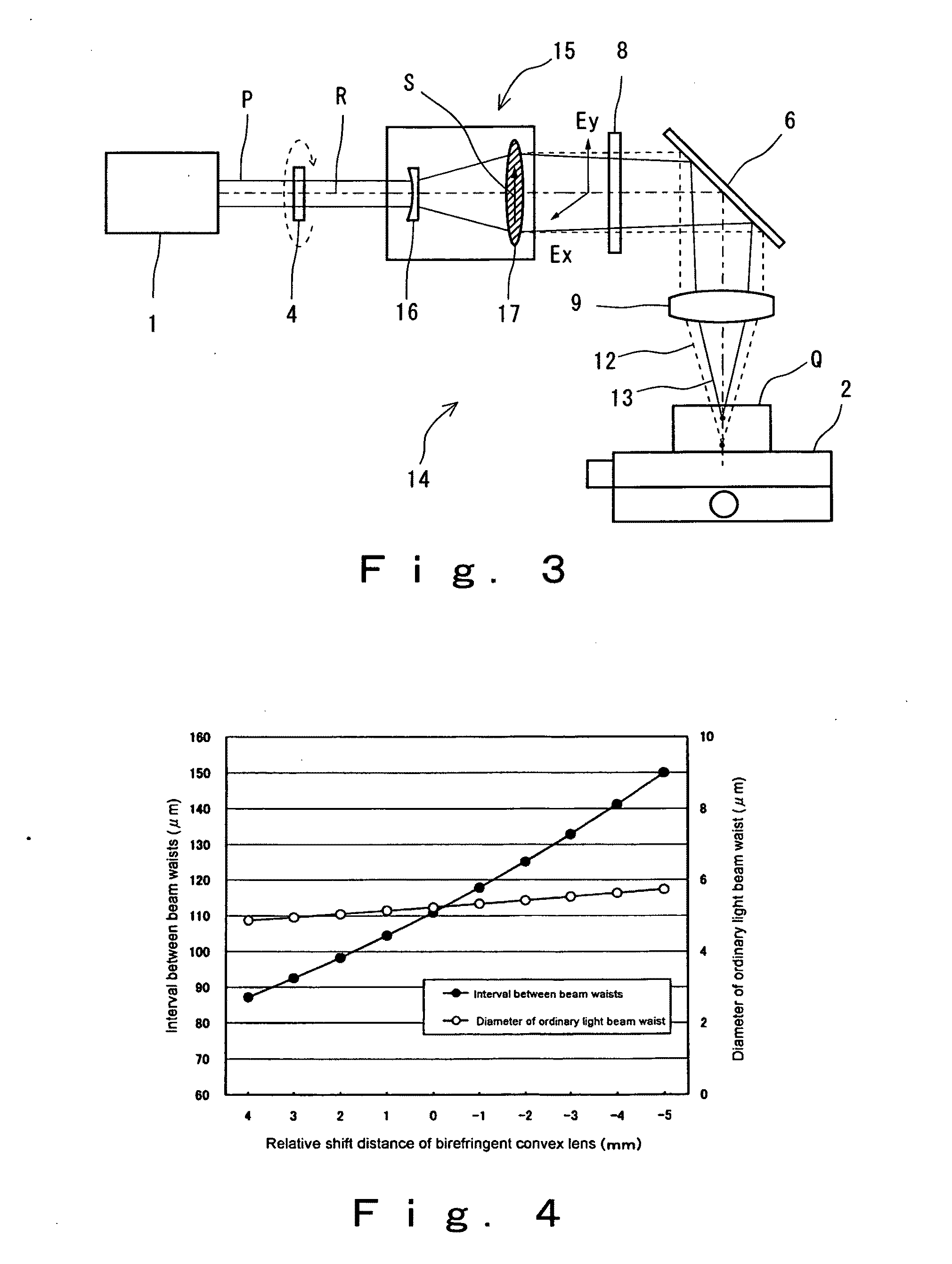
[0073]Using an irradiation optical system provided with at least a light source, a beam expander, a half-wave plate and a light converging lens, one or two beam waists were arranged inside a borosilicate glass which can be readily observed on processing traces, whereby a processed groove was formed. Thereafter, a cross-sectional view orthogonal to this processed groove was photographed.

[0074]The beam expander used in Examples 1 and 2 was provided with a concave lens and a convex lens having birefringency, and was configured so as to make the interval between both lenses be variable. By changing the interval between both lenses (Lm), the interval of two beam waists formed on the optical axis can be altered. In addition, when the half-wave plate used in Examples 1 and 2 was rotated around the optical axis of the irradiation optical system, laser power distribution at two light converging spots can be altered.

experiment 2

Example 3 and Example 4

[0079]The experimental system was similar to those of Example 1 and Example 2 in the Experiment 1. In Experiment 2, the interval between the expander lenses Lm was kept constant, and the half-wave plate was rotated around the optical axis of the irradiation optical system to alter the power distribution of two waists.

[0080]The processing conditions and experimental results are shown in Table 4 below, and FIG. 9 and FIG. 10.

Processing conditionsUnitExample 3Example 4Material of processed object—borosilicate borosilicateglassglassLaser wavelengthnm355355Mean power on theW0.610.61processed faceQ switch ratekHz3535Processing speedmm / s100100Number of light converging waistspiece1 (lower alone)2(spot number)Interval between expander lenses Lmmm (relativefixedfixedvalue)Power component: upper / lower waist%0 / 10030 / 70Waist intervalμmabout 190about 90Upperdiameter of beam waistμmφ—3.2Waistpower densityW / cm2—0.9 × 10¹⁰Lowerdiameter of beam waistμmφ3.03.0Waistpower density...


PUM

PropertyMeasurementUnit
wavelengthaaaaaaaaaa

Abstract

Provided is a laser irradiation device for use in laser processing, and a laser processing method performed using the same. Provided is a laser irradiation device including: a light source that emits a laser beam; and an irradiation optical system which has one or a plurality of lenses, and is provided for light-guiding and light-converging of the laser beam emitted from the light source to the target substance, in which a birefringent material is used as a material entity of at least one lens of the irradiation optical system. Also provided is a laser processing method. The irradiation optical system may have a beam expander having a first lens that is a concave lens or a convex lens, and a second lens that is a convex lens, in the order along the laser-beam travel direction, the beam expander being configured so as to make the interval between the first lens and the second lens variable, in which a birefringent material may be used as a material entity of the first lens and / or the second lens. Thus, the interval between the lenses can be changed by a convenient operation, whereby relative positions between the plurality of beam waists (interval) can be easily regulated.

Description

TECHNICAL FIELD[0001]The present invention relates to a laser irradiation device for use in laser processing of ceramics, etc., and a laser processing method performed using the same.BACKGROUND ART[0002]Circuit boards and the like equipped with electronic parts have been produced using a hard and brittle material such as a ceramics material, glass material, silicon material or the like. In order to cut a board formed from such a hard and brittle material, it is necessary to form a groove on the surface of the board, or to form fine holes inside the board. As means for the formation, laser processing has been widely used. In laser processing, a laser beam emitted from a light source is converged using an irradiation optical system such as a lens, and a laser converged spot (beam waist) having an elevated power density is irradiated on the surface or the interior of the board to execute the processing.[0003]At present, in attempts to miniaturize electronic parts and to improve process...

Claims


Application Information

Patent Timeline
Patent Type & Authority Applications(United States)
IPC IPC(8): G21K5/00B23K26/08H01S3/00
CPCB23K26/0057B23K26/4075B23K26/0617B23K26/40B23K2103/50B23K26/53B23K26/067B23K26/064B23K26/08H01S3/00
Inventor KAJIKAWA, TOSHIKAZU
Owner SEISHIN TRADING
Learn More