
Laser material processing tool

a technology of laser material and processing tool, which is applied in the field of laser material processing tool, can solve the problems of serious safety and security concerns, and reducing the production rate, so as to improve the protection of optics, improve the effect of debris removal and wide fluid jet coverag

Active Publication Date: 2012-08-02
HALLIBURTON ENERGY SERVICES INC +1
View PDF6 Cites 9 Cited by
  • Summary
  • Abstract
  • Description
  • Claims
  • Application Information

AI Technical Summary

Benefits of technology

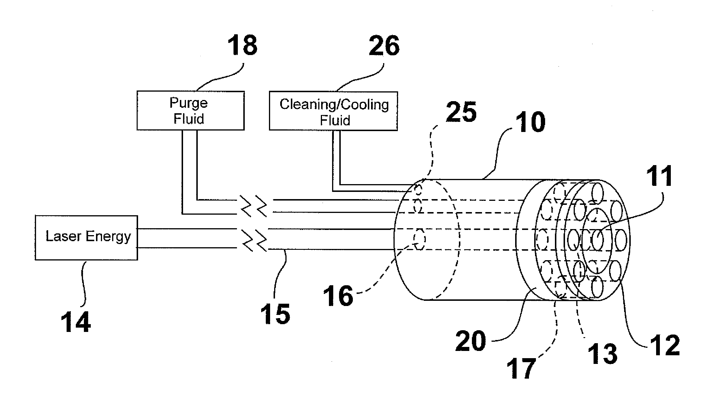
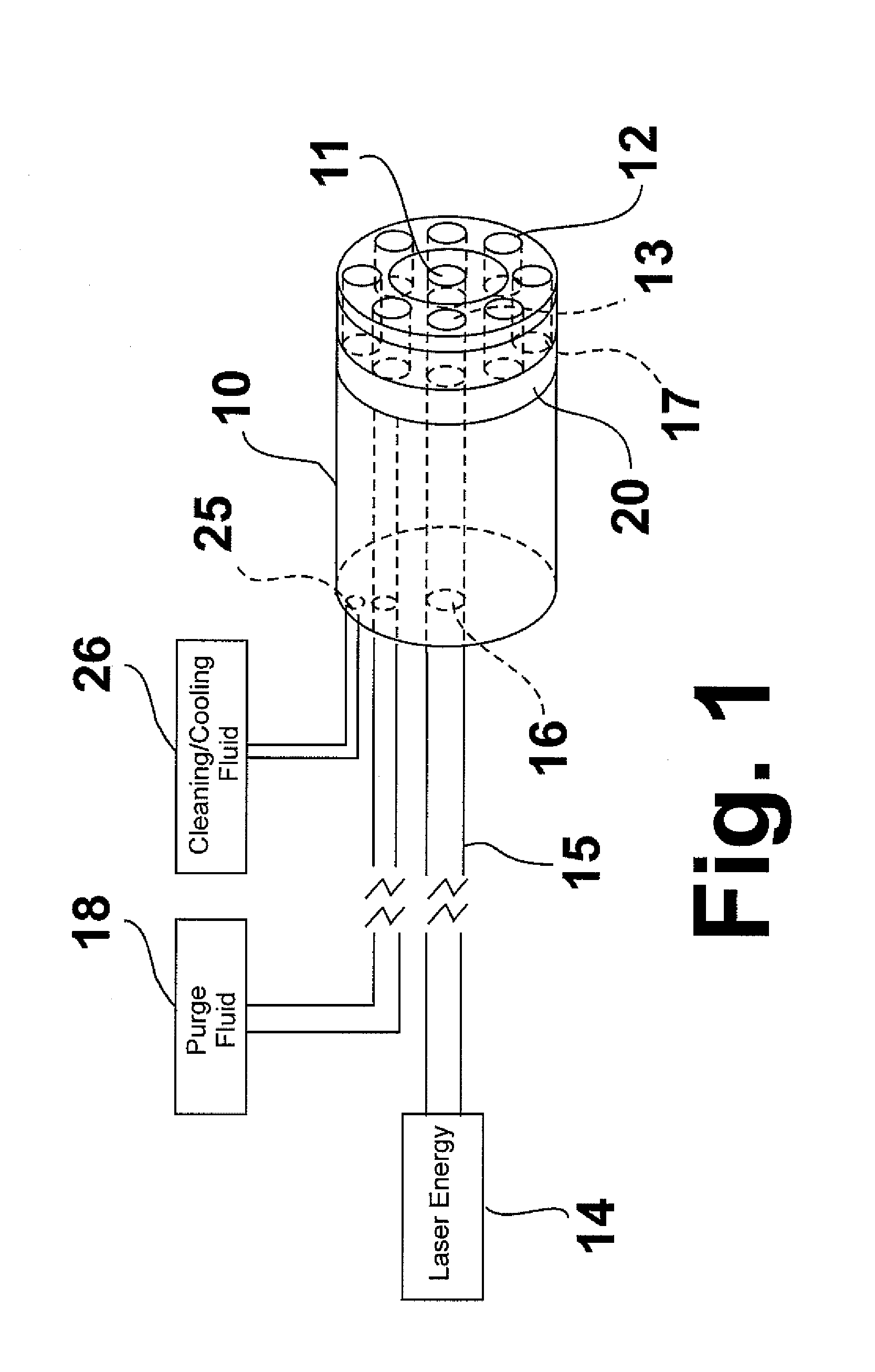
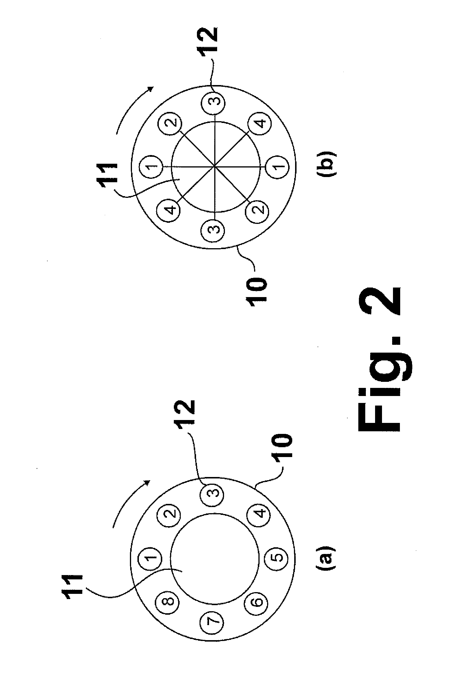
The invention is a laser-based material processing tool that reduces the likelihood of melt or slag residue deposits on the edges of boreholes and produces a deeper borehole with less taper than conventional tools. It includes a laser head assembly with a laser energy outlet, an optical emitter, laser energy control means, and an automated purge fluid emitter. The tool can be used for various material processing applications. It also has features such as dross control, improved debris removal, and wider fluid jet coverage. The tool allows for greater fluid medium choices because the fluid jets do not necessarily cross or co-propagate along the laser beam path.

Problems solved by technology

In addition to the limitations of opening size and hole depth, there are numerous problems with this approach.
First, the melt or debris from shaped charges usually reduces the permeability of the producing formations resulting in a substantial reduction in production rate.
Second, these techniques involve the transportation and handling of high power explosives and are causes of serious safety and security concerns.
Third, the energy jet into the formation also produces fine grains that can plug the pore throat, thereby reducing the production rate.
Water jetting can also be used for wellbore perforation; however, the opening that is created is generally not very uniform.
Highly viscous fluids do not flow easily.
In extreme cases, these factors reduce the flow rate to zero, halting production entirely.
With known laser-based devices for wellbore perforation, perforation depths have been limited to about 4 inches after which further penetration is hampered by hole taper issues and the lack of efficient debris removal.
In addition, once begun, hole tapering is difficult to correct with a laser processing beam oriented parallel to the perforation axis due to the increased surface area presented by the side walls.
Furthermore, reflections from grazing angle incidence tend to reflect laser energy into the central regions of the opening / perforation, creating excessive heating in the center, causing uneven material removal, opening shapes, and opening quality.
In rock / refractory applications, the central material could glassify before the sidewall material is spalled, thereby creating poor quality openings and reducing the efficiency of material removal.
However, with conventional drill lasers, there is also the possibility that melt residue or slag deposits on the edge of the borehole.
Such melt or slag residue deposits are undesirable because they can significantly influence the borehole quality.

Method used


Image

  • Laser material processing tool
  • Laser material processing tool
  • Laser material processing tool

Examples


Embodiment Construction

[0021]Without intending to limit the material processing applications of this invention, the laser material processing tool of this invention is primarily intended for the processing of materials within a wellbore. In addition to being able to operate generally in the harsh downhole environment, the laser material processing tool is able to generate substantially uniform, taper-controlled holes, including holes having minimal taper, in downhole materials for wellbore perforation and perform other downhole activities requiring material processing. In general, the tool comprises two primary components for material processing—a laser beam emitter for heating the material to be processed and a gaseous and / or liquid purge fluid emitter for facilitating the removal of material from the material opening created by the laser beam.

[0022]FIG. 1 shows a laser material processing tool in accordance with one embodiment of this invention. As shown therein, the tool comprises a laser head assembly...


PUM

PropertyMeasurementUnit
diameteraaaaaaaaaa
perforation depthsaaaaaaaaaa
energyaaaaaaaaaa

Abstract

An apparatus for laser drilling including a laser beam emitter disposed within a housing having at least one laser beam outlet and at least one purge fluid outlet. At least one actuated nozzle is disposed within the housing for providing a purge fluid through the purge fluid outlet and having functional control for synchronized programmable activation patterns. Laser beam control is provided for directing a laser beam over a target surface.

Description

BACKGROUND OF THE INVENTION[0001]1. Field of the Invention[0002]This invention relates to a laser-based tool for processing materials. In one aspect, this invention relates to a laser material processing tool for use in wellbore drilling. In another aspect, this invention relates to a laser material processing tool for material cutting. In another aspect, this invention relates to a laser material processing tool for material spalling. In yet another aspect, this invention relates to a laser material processing tool for material thermal treatment, e.g. annealing. In yet another aspect, this invention relates to a laser material processing tool for material curing. In yet another aspect, this invention relates to a laser material processing tool for material surface conditioning.[0003]2. Description of Related Art[0004]Fluid flow into a completed subterranean wellbore is initiated by perforation of the well casing or liner. Conventionally, such perforations are created using shaped c...

Claims


Application Information

Patent Timeline
Patent Type & Authority Applications(United States)
IPC IPC(8): H01S3/10
CPCB23K26/0643B23K26/1405B23K26/041B23K26/386E21B7/14B23K26/1476B23K26/042B23K26/142B23K26/1438B23K26/382B23K26/389
Inventor WILKIEL, LLOYDSKINNER, NEAL GREGORYHUNTER, TIMOTHY HOLIMAN
Owner HALLIBURTON ENERGY SERVICES INC
Learn More